|
THE MINISTRY OF TRANSPORT OF
VIETNAM
-------
|
SOCIALIST REPUBLIC OF VIETNAM
Independence - Freedom - Happiness
----------------
|
|
No. 14/2024/TT-BGTVT
|
Hanoi, May 29, 2024
|
CIRCULAR
NATIONAL
TECHNICAL REGULATION ON MARINE POLLUTION PREVENTION SYSTEMS OF SHIPS
Pursuant to the Vietnam Maritime
Code dated November 25 of 2015;
Pursuant to the Law on Technical
Regulations and Standards dated June 29, 2006;
Pursuant to Decree No. 56/2022/ND-CP
dated August 24, 2022 of the Government on functions, tasks, powers, and
organizational structures of Ministry of Transport;
At request of Director of Science
-Technology and Environment Department and Director of Vietnam Register;
The Minister of Transport promulgates
Circular on National Technical regulation on marine pollution prevention
systems of ships.
Article 1. The National Technical Regulation on
marine pollution prevention systems of ships No. QCVN 26:2024/BGTVT is attached
hereto.
...
...
...
Hãy đăng nhập hoặc đăng ký Thành viên
Pro tại đây để xem toàn bộ văn bản tiếng Anh.
1. This Circular comes into force
from December 01 of 2024.
2. Annul Circular No.
09/2019/TT-BGTVT dated March 1 of 2019 of the Minister of Transport on National
Technical Regulation on marine pollution prevention systems of ships.
3. Transition clauses: Ships built
before the effective date hereof shall conform to QCVN 26:2018/BGTVT unless
otherwise specified under QCVN 26:2018/BGTVT.
Article 3. Organizing implementation
Chief of Ministry Office, Chief of
Ministry Inspectorate, Directors, Director of Vietnam Register, heads of
agencies and entities affiliated to the Ministry of Transport, relevant
organizations and individuals are responsible for the implementation of this
Circular./.
PP. MINISTER
DEPUTY MINISTER
Nguyen Xuan Sang
...
...
...
Hãy đăng nhập hoặc đăng ký Thành viên
Pro tại đây để xem toàn bộ văn bản tiếng Anh.
NATIONAL
TECHNICAL REGULATION ON MARINE POLLUTION PREVENTION SYSTEMS OF SHIPS
Foreword
The National Technical Regulation on
marine pollution prevention systems of ships (No. QCVN 26:2024/BGTVT) is
compiled by Vietnam Register, presented by Science -Technology and Environment
Department, appraised by the Ministry of Science and Technology, promulgated by
Minister of Transport under Circular No. 14/2024/TT-BGTVT dated May 29 of 2024.
The QCVN 26:2024/BGTVT replaces QCVN
26:2018/BGTVT (National Technical Regulation on marine pollution prevention
systems of ships).
NATIONAL
TECHNICAL REGULATION ON MARINE POLLUTION PREVENTION SYSTEMS OF SHIPS
TABLE
OF CONTENTS
...
...
...
Hãy đăng nhập hoặc đăng ký Thành viên
Pro tại đây để xem toàn bộ văn bản tiếng Anh.
1.1. Scope and regulated entities
1.2. Reference and definitions
II
TECHNICAL PROVISIONS
PART 1
GENERAL PROVISIONS
Chapter 1 General provisions
1.1 General provisions
PART 2
INSPECTION
Chapter 1 General provisions
1.1 General provisions
...
...
...
Hãy đăng nhập hoặc đăng ký Thành viên
Pro tại đây để xem toàn bộ văn bản tiếng Anh.
1.3. Examination and verification of
certificates
Chapter 2 Initial inspection
2.1 Initial inspection in
shipbuilding
2.2 Initial inspection without
attendance of VR in shipbuilding
Chapter 3 Regular inspection
3.1 Annual inspection
3.2 Intermediate inspection
3.3 Periodic inspection
Chapter 4 Irregular inspection
...
...
...
Hãy đăng nhập hoặc đăng ký Thành viên
Pro tại đây để xem toàn bộ văn bản tiếng Anh.
PART 3
STRUCTURE AND EQUIPMENT PREVENTING POLLUTION CAUSED BY OIL
Chapter 1 General provisions
1.1 Scope and definitions
1.2 General requirements
Chapter 2 Equipment preventing
pollution caused by oil from machinery space
2.1 General provisions
2.2 Oil residue containment and
discharge
2.3 Oil filters and oil-contaminated
ballast water chest
2.4 Installation requirements
...
...
...
Hãy đăng nhập hoặc đăng ký Thành viên
Pro tại đây để xem toàn bộ văn bản tiếng Anh.
3.1 General provisions
3.2 Hull structure
3.3 Equipment and pipe arrangement
3.4 Crude oil washing system
Chapter 4 Regulations for transition
period
4.1 General provisions
4.2 General requirements
4.3 Equipment for preventing pollution
caused by oil transported in bulk
PART 4
STRUCTURE AND EQUIPMENT FOR PREVENTING POLLUTION CAUSED BY DISCHARGE OF NOXIOUS
LIQUID TRANSPORTED IN BULK
...
...
...
Hãy đăng nhập hoặc đăng ký Thành viên
Pro tại đây để xem toàn bộ văn bản tiếng Anh.
1.1 General provisions
1.2 Definitions
Chapter 2 Structure and equipment
2.1 General provisions
2.2 Requirements regarding
structural and equipment installation
Chapter 3 Equipment for preventing
discharge of noxious liquid substances
3.1 General provisions
3.2 Pre-wash system
3.3 Stripping system
...
...
...
Hãy đăng nhập hoặc đăng ký Thành viên
Pro tại đây để xem toàn bộ văn bản tiếng Anh.
3.5 Discharge system into reception
facilities
3.6 Ventilated washing system
3.7 Segregated ballast tank
PART 5
SHIPBOARD OIL POLLUTION EMERGENCY PLAN
Chapter 1 General provisions
1.1 General provisions
Chapter 2 Technical requirements
2.1 General provisions
2.2 Entries under Shipboard oil
pollution emergency plan
...
...
...
Hãy đăng nhập hoặc đăng ký Thành viên
Pro tại đây để xem toàn bộ văn bản tiếng Anh.
2.4 Additional requirements for oil
tankers of 5.000 tonnage and above
PART 6
SHIPBOARD MARINE POLLUTION EMERGENCY PLAN FOR NOXIOUS LIQUID SUBSTANCES
Chapter 1 General provisions
1.1 General provisions
Chapter 2 Technical requirements
2.1 General provisions
2.2 Entries in Shipboard marine
pollution emergency plan for noxious liquid substances
2.3 Appendices of Shipboard marine
pollution emergency plan for noxious liquid substances
PART 7
EQUIPMENT FOR PREVENTING POLLUTION BY SEWAGE
...
...
...
Hãy đăng nhập hoặc đăng ký Thành viên
Pro tại đây để xem toàn bộ văn bản tiếng Anh.
1.1 General provisions
Chapter 2 Equipment for preventing pollution
by sewage
2.1 General provisions
2.2 Regulations on equipment
PART 8
EQUIPMENT FOR PREVENTING SHIPBOARD AIR POLLUTION
Chapter 1 General provisions
1.1 General provisions
1.2 General clauses
Chapter 2 Equipment for preventing
shipboard air pollution
...
...
...
Hãy đăng nhập hoặc đăng ký Thành viên
Pro tại đây để xem toàn bộ văn bản tiếng Anh.
2.2 Sulfur oxide (SOx) and particulate
matters
2.3 Vapour collection system
2.4 Waste incinerators
Chapter 3 Energy efficiency of ships
3.1 General provisions
3.2 Attained energy efficiency
design index (attained EEDI)
3.3 Attained energy efficiency
existing ship index (attained EEXI)
3.4 Required energy efficiency
design index (required EEDI)
3.5 Required energy efficiency
existing ship index (required EEXI)
...
...
...
Hãy đăng nhập hoặc đăng ký Thành viên
Pro tại đây để xem toàn bộ văn bản tiếng Anh.
3.7 Declaration of conformity
regarding shipboard fuel consumption data and carbon intensity reports
3.8 Collecting, reporting, and
storage of data relating to energy consumption data report
3.9 Carbon intensity
PART 9
PREVENTION OF POLLUTION CAUSED BY GARBAGE
Chapter 1 General provisions
1.1 General provisions
1.2 General provisions pertaining to
prohibition against sea dumping
Chapter 2 Placard, garbage
management plan and garbage record book
2.1 Placard, garbage management plan
and garbage record book
...
...
...
Hãy đăng nhập hoặc đăng ký Thành viên
Pro tại đây để xem toàn bộ văn bản tiếng Anh.
Chapter 3 Garbage containment station
and garbage collection equipment
3.1 Garbage containment station
3.2 Garbage bins
PART
10 STRUCTURE AND EQUIPMENT FOR PREVENTING POLLUTION FROM SHIPS OPERATING IN
POLAR SEAS
Chapter 1 General provisions
1.1 General provisions
1.2 Definitions
Chapter 2 Prevention of pollution
caused by oil spill
2.1 Shipboard oil pollution
emergency plan and other issues
...
...
...
Hãy đăng nhập hoặc đăng ký Thành viên
Pro tại đây để xem toàn bộ văn bản tiếng Anh.
Chapter 3 Prevention of pollution
caused by noxious liquid substances
3.1 Shipboard sea pollution
emergency plan and other issues
3.2 Structure and equipment
III
REGULATIONS ON MANAGEMENT
Chapter 1 Regulation on
certification
1.1 General provisions
1.2 Certificates issued to the ship
1.3 Effective period of certificates
1.4 Storage, re-issuance, and return
of certificates
...
...
...
Hãy đăng nhập hoặc đăng ký Thành viên
Pro tại đây để xem toàn bộ văn bản tiếng Anh.
Chapter 2 Document management
2.1 General provisions
2.2 Issuance of inspection documents
2.3 Document management
IV RESPONSIBILITIES
OF ORGANIZATIONS AND INDIVIDUALS
1.1 Responsibilities of ship owners,
facilities for designing, building, modifying, and repairing ship, facilities
for manufacturing engines, shipboard equipment for preventing pollution
1.2 Responsibilities of Vietnam
Register
V ORGANIZING
IMPLEMENTATION
Appendix Guidelines on discharging
noxious liquid substances
...
...
...
Hãy đăng nhập hoặc đăng ký Thành viên
Pro tại đây để xem toàn bộ văn bản tiếng Anh.
1.2 Discharge of noxious liquid
substances
1.3 Discharge of noxious liquid
substances in Antarctic sea
1.4 Liquid substances that are not
noxious
NATIONAL
TECHNICAL REGULATION ON MARINE POLLUTION PREVENTION SYSTEMS OF SHIPS
I
GENERAL PROVISIONS
1.1 Scope and regulated entities
1.1.1 Scope
This National Technical Regulation
(hereinafter referred to as “Regulation”) prescribes inspection, structure and
equipment for preventing pollution installed on Vietnamese ships, fixed and
mobile rigs at sea, floating storage units for petroleum exploration and
production in Vietnamese seas (hereinafter referred to as “ships”).
...
...
...
Hãy đăng nhập hoặc đăng ký Thành viên
Pro tại đây để xem toàn bộ văn bản tiếng Anh.
This Regulation applies to
organizations and individuals engaging in activities relating to shipboard
pollution prevention systems from ships under 1.1.1 that are the Vietnam
Register (hereinafter referred to as “VR”), ship owners, facilities for
designing, building, modifying, and repairing ships, facilities for manufacturing
engines, shipboard equipment for preventing pollution.
1.2 Reference and definitions
1.2.1 Reference documents used in
this document
1 National Technical Regulation on classification and
construction of sea-going steel ships.
2 National Technical Regulation on classification and
construction of sea-going high speed ships.
3 National Technical Regulation on classification and
technical supervision of mobile rigs at sea.
4 National Technical Regulation on classification and
technical supervision of fixed rigs at sea.
5 National Technical Regulation on classification and
technical supervision of floating storage unit
6 Circular No. 20/2022/TT-BGTVT dated July 29, 2022 of the Minister of
Transport.
...
...
...
Hãy đăng nhập hoặc đăng ký Thành viên
Pro tại đây để xem toàn bộ văn bản tiếng Anh.
8 Circular No. 55/2019/TT-BGTVT dated December 31 of 2019 of Minister of
Transport.
9 International Convention for the Prevention of Pollution
from Ships of 1973 amended by relevant Protocol of 1978 and Protocol of 1997.
10 Amended International Convention for the
Safety of Life at Sea, 1974.
11 Relevant Resolutions and Circulars
of International Maritime Organization.
12 International code for ships
operating in polar waters (Polar Code).
13 International Bulk Chemical Code
(IBC Code) of the International Maritime Organization (IMO).
1.2.2 Definitions
1 In this document, the terms below have the meaning
attributed to them as follows unless otherwise specified in specific Part of
the Regulation:
(1) “Oil” refers to petroleum and
includes crude oil, lubricating oil, light oil, kerosene, gasoline, and other
oil types specified under relevant standards and regulations.
...
...
...
Hãy đăng nhập hoặc đăng ký Thành viên
Pro tại đây để xem toàn bộ văn bản tiếng Anh.
(3) “Liquid substances” refers to
any substance with maximum absolute pressure measured at 37,8 oC of
0,28 MPa.
(4) ”Noxious liquid substances” refers
to any substance placed under category X, Y, or Z under Schedule 8E/17.1 and
Schedule 8E/18.1 Part 8E Section II in the National Technical Regulation on
classification and construction of sea-going steel ships or other liquid
substances temporarily deemed by Point 6.3 Annex II of MARPOL as substances of
category X, Y, or Z.
(5) “Fuel oil” refers to oil stored
aboard ships for use as fuel for primary and secondary engines of ships.
(6) “Oil tanker” refers to a ship
built for bulk transport of liquid products using the majority of its cargo
space or a ship built for bulk transport of liquid products using a part of its
cargo space of minimum volume of 200 m3 (other than ships with cargo
spaces converted specifically for bulk transport of non-oil products).
(7) “Ships carrying bulk noxious
liquid substances” refers to a ship built for bulk transport of noxious liquid
substances in the majority of its cargo spaces or a ship built for bulk
transport of noxious liquid substances in a part of its cargo spaces (other
than ships with cargo spaces converted specifically for bulk transport of goods
that are not noxious liquid substances transported in bulk).
(8) “General cargo ships” refers to
a ship designed for bulk transport or transport of oil or solid goods.
(8) “Segregated ballast” refers to
ballast water introduced into a permanent ballast tank or tank storing goods
other than oil or noxious substances as defined under this Regulation and is
completely separated from the cargo system.
(10) “Length” (Lf) is 96% of the total
length on the waterline at 85% of the least molded depth, or as the length
measured from the fore side of the stem to the axis of the rudder stock on the
waterline, if that is greater. In the case of a ship having a rake of keel, the
waterline serving length calculation shall be parallel to the designed
waterline. Length (Lf) uses the unit of meter.
(11) “Forward and after
perpendiculars” refers to perpendiculars measured at both ends of the length
(Lf). Forward perpendicular travels through intersection of the forward side of
the stem with the waterline serving length calculation.
...
...
...
Hãy đăng nhập hoặc đăng ký Thành viên
Pro tại đây để xem toàn bộ văn bản tiếng Anh.
(13) “Breadth” (B) refers to the
maximum breadth of the ship measured amidships to the moulded line of the frame
in a ship with a metal shell and to the outer surface of the hull in a ship
with a shell of any other material. Breadth (B) uses the unit of meter.
(14) “Deadweight” (DW) refers to
the difference in tonnes between the displacement of a ship in water of a
relative density of 1.025 at the load waterline corresponding to the assigned
summer freeboard and the light ship weight, in tonne.
(15) “Light ship weight” refers to
displacement of the vessel in metric tons (long tons) with no cargo, fuel, lubricating
oil, ballast water, fresh water nor feed water in tanks, no consumable stores,
and no passengers or crew nor their effects. Weight of other substances aboard
the ship for use by firefighting fixtures (such as freshwater, CO2, dry
chemical powder, foaming agent, etc.) must be included in light ship weight.
(16) “Permeability” of a space
refers to the ratio of the volume within the space which is assumed to be
occupied by the water to the gross tonnage of that space.
(17) “Crude oil” refers to a
mixture of liquid hydrocarbon naturally formed in the Earth’s crust, may or may
not be processed for transport, including:
(a) Crude oil from which distilled
components have been removed;
(b) Crude oil to which distilled
components have been added.
(18) “Volume” and “Area” of a ship
conform to design illustration in all circumstances.
(19) “Crude oil tanker” refers to
an oil tanker carrying crude oil.
...
...
...
Hãy đăng nhập hoặc đăng ký Thành viên
Pro tại đây để xem toàn bộ văn bản tiếng Anh.
(21) “Equipment preventing
discharge of noxious liquid substances” consists of pre-wash system, stripping
system, discharge system below waterline, discharge system into reception
facilities, washing system utilizing ventilation, segregated ballast tank.
(22) “Ship operating on
international voyage” refers to a ship disembarking from port of one country to
port of another country.
(23) “Residue” refers to noxious
liquid substances remaining in tanks and pipes after the goods have been delivered.
(24) “Designated annual inspection
date” corresponds to but does not include expiry date of International Oil
Pollution Prevention Certificate (or Oil Pollution Prevention Certificate).
(25) “Ship built” refers to a ship
with laid keel or ship undergoing similar stage of shipbuilding process.
Similar stage of shipbuilding
process is a stage where:
(a) Built structures somewhat
resemble a ship; or
(b) Ship construction process has
completed a minimum of 50 tonne or 1% of estimated load of structural
materials, whichever is lower.
(26) “Oil residues” refers to waste
oil products created during normal ship operation such as products created by
filtering of fuel oil, lubricating oil of primary and secondary engines, waste
oils separated from oil filters, waste oils collected from trays, discarded
hydraulic fluid and lubricating oils.
...
...
...
Hãy đăng nhập hoặc đăng ký Thành viên
Pro tại đây để xem toàn bộ văn bản tiếng Anh.
(28) “Oil-contaminated ballast
water” refers to water potentially contaminated with oil due to leak or
performance of maintenance tasks in machinery space. Any liquid entering dry
suction system, including dry suction wells, dry suction pipes, top of tank or
ballast tanks is considered oil-contaminated ballast water.
(29) “Oil-contaminated ballast
water tank” refers to a tank containing oil-contaminated ballast water for the
purpose of discharge, exchange, or disposal.
(30) “Marine pollution prevention
equipment” refers to structures and equipment detailed under Parts 3, 4, 7, 8,
and 9, including response plans under Parts 5 and 6 Section II hereof.
(31) “Mobile offshore platform”
refers to a mobile platform defined under National Technical Regulation on
classification and technical supervision of mobile offshore platform.
(32) “Fixed offshore platform”
refers to a fixed platform defined under National Technical Regulation on
classification and technical supervision of fixed offshore platform.
(33) “Floating storage unit” refers
to a storage unit defined under National Technical Regulation on classification
and technical supervision of floating storage units.
(34) “Restriction grade” refers to
additional ship grade marker in respect of ships with limited operating range
under 2.1.4-1(1) and (2) of Part 1A Section II of National Technical Regulation
on classification and construction of sea-going steel ships.
(35) “Nearest land” or “from
nearest land” refers to from the baseline from which the territorial sea of the
territory in question is established in accordance with international law,
except for the purposes of the present Convention 'from the nearest land' off
the north-eastern coast of Australia shall mean from a line drawn from a point
on the coast of Australia in:
latitude 11°00' S, longitude 142°08'
E
...
...
...
Hãy đăng nhập hoặc đăng ký Thành viên
Pro tại đây để xem toàn bộ văn bản tiếng Anh.
thence to a point latitude 10°00' S,
longitude 142°00' E,
thence to a point latitude 9°10' S,
longitude 143°52' E,
thence to a point latitude 9°00' S,
longitude 144°30' E,
thence to a point latitude 10°41' S,
longitude 145°00' E,
thence to a point latitude 13°00' S,
longitude 145°00' E,
thence to a point latitude 15°00' S,
longitude 146°00' E,
thence to a point latitude 17°30' S,
longitude 147°00' E,
thence to a point latitude 21°00' S,
longitude 152°55' E,
thence to a point latitude 24°30' S,
longitude 154°00' E,
...
...
...
Hãy đăng nhập hoặc đăng ký Thành viên
Pro tại đây để xem toàn bộ văn bản tiếng Anh.
(36) International code for ships
operating in polar waters (Polar Code) is a code consisting of introduction,
Part I-A, Part II-A, Part I-B, and Part II-B approved by Resolutions
MSC.385(94) and MEPC.264(68) and revisions thereto under the conditions that:
(a) The revisions relating to
environment in the introduction section and Chapter 1 Part II-A of the Code are
approved and coming into force in a manner appropriate to clauses under Article
16 of the applicable MARPOL, relating to revision procedures applicable to
headings of an Annex;
(b) Revisions to Part II-B of the
Code are approved by Marine Environment Protection Committee (MEPC) in a manner
appropriate to procedures of the Committee.
(37) Appraisal (or approval) means
VR’s inspection and re-examination of drawing, design dossiers, instructions,
procedures, or other details for the purpose of inspecting compliance with
relevant requirements under technical regulations, standards, or other
reference documents when requested.
1.2.3 Abbreviations
1 This Regulation contains the following abbreviations:
(1) IMO: International Maritime
Organization.
(2) MEPC: Marine Environment
Protection Committee of IMO.
(3) ICS: International Chamber of
Shipping.
...
...
...
Hãy đăng nhập hoặc đăng ký Thành viên
Pro tại đây để xem toàn bộ văn bản tiếng Anh.
(5) SOLAS, 1974: International
Convention for the Safety of Life at Sea, 1974, amended.
(6) MARPOL (or Convention):
International Convention for the Prevention of Pollution from Ships, 1973,
amended by relevant Protocols in 1978 and 1997.
(7) Annex I: Annex I - MARPOL
regulations on prevention of pollution by oil.
(8) Annex II: Annex II - MARPOL
regulations on Control of Pollution by Noxious Liquid Substances in Bulk.
(9) Annex III: Annex III - MARPOL
regulations on Prevention of Pollution by Harmful Substances Carried by Sea in
Packaged Form.
(10) Annex IV: Annex IV - MARPOL
regulations on Prevention of Pollution by Sewage from Ships.
(11) Annex V: Annex V - MARPOL
regulations on Prevention of Pollution by Garbage from Ships.
(12) Annex VI: Annex VI - MARPOL
regulations Prevention of Air Pollution from Ships.
(13) SBT: Segregated ballast tank.
...
...
...
Hãy đăng nhập hoặc đăng ký Thành viên
Pro tại đây để xem toàn bộ văn bản tiếng Anh.
(15) COW: Crude oil washing system.
(16) IGS: Inert gas system.
(17) PL: Protective locations of
segregated ballast tanks.
(18) ppm: parts per million of oil
to water by volume.
(19) Abbreviations under
Resolutions of the IMO Council:
- A.393(X): Resolution No. 393(X)
dated 14 November 1977 - Recommendation on international performance and test
specification for oily-water separation equipment and oil content meters.
- A.586(14): Resolution No. 586(14)
dated 20 November 1985 - Revised guidelines and specifications for oil
discharge monitoring and control systems for oil tankers.
- A.496(XII): Resolution No.
496(XII) - Guidelines and specifications for oil discharge monitoring and
control systems for oil tankers.
(20) Abbreviations in Circulars and
Resolutions of the MEPC:
...
...
...
Hãy đăng nhập hoặc đăng ký Thành viên
Pro tại đây để xem toàn bộ văn bản tiếng Anh.
- MEPC.13(19): Resolution No. 13(19)
dated 09 December 1983 - Guidelines for plan approval and installation survey
of oil discharge monitoring and control systems for oil tankers and
environmental testing of control sections thereof.
- MEPC.20(22): Resolution No. 20(22)
dated 05 December 1985 - Adoption of the code for the construction and of ships
carrying dangerous chemicals in bulk.
- MEPC.60(33): Resolution No. 60(33)
dated 30 October 1992 - Guidelines and specifications for pollution prevention
equipment for machinery space bilges of ships.
- MEPC.76(40): Resolution No. 76(40)
dated 25 September 1997 - Standard specification for shipboard incinerators.
- MEPC.94(46): Resolution No. 94(46)
dated 27 April 2001 - Condition Assessment Scheme.
- MEPC.107(49): Resolution No.
107(49) dated 18 July 2003 - Revised guidelines and specifications for
pollution prevention equipment for machinery space bilges of ships.
- MEPC.108(49): Resolution No.
586(49) dated 18 November 2003 - Revised guidelines and specifications for oil
discharge monitoring and control systems for oil tankers.
- MEPC.182(59): Resolution No.
182(59) dated 17 July 2009 - 2009 Guidelines for the sampling of fuel oil for
determination of compliance with the revised MARPOL Annex VI.
- MEPC.184(59): Resolution No.
184(59) dated 17 July 2019 - 2009 Guidelines for Exhaust Gas Washing Systems.
...
...
...
Hãy đăng nhập hoặc đăng ký Thành viên
Pro tại đây để xem toàn bộ văn bản tiếng Anh.
- MEPC.198(62): Resolution No.
198(62) dated 15 July 2011 - 2011 Guidelines addressing additional aspects to
the NOX Technical Code 2008 with regard to particular requirements
related to marine diesel engines fitted with selective catalytic reduction
(SCR) systems.
- MEPC.215(63): Resolution No.
215(63) dated 02 March 2012 - Guidelines for calculation of reference lines for
use with the energy efficiency design index (EEDI).
- MEPC.220(63): Resolution No.
220(63) dated 02 March 2012 - 2012 Guidelines for the development of garbage
management plans.
- MEPC. 227(64): Resolution No.
227(64) dated 05 October 2012 - 2012 Guidelines on implementation of effluent
standards and performance tests for sewage treatment plants.
- MEPC.230(65): Resolution No.
230(65) dated 17 May 2013 - 2013 Guidelines as required by Regulation 13.2.2 of
MARPOL Annex VI in respect of non-identical replacement engines not required to
meet the Tier III limit.
- MEPC.232(65): Resolution No.
232(65) dated 17 May 2013 - 2013 Interim guidelines for determining minimum
propulsion power to maintain the manoeuvrability of ships in adverse
conditions.
- MEPC.233(65): Resolution No.
233(65) dated 17 May 2013 - 2013 Guidelines for calculation of reference lines
for use with the energy efficiency design index (EEDI) for cruise passenger
ships having non-conventional propulsion.
- MEPC.240(65): Resolution No.
240(65) dated 17 May 2013 - 2013 Revisions to the Revised guidelines and
specifications for oil discharge monitoring and control systems for oil
tankers.
- MEPC.244(66): Resolution No.
244(66) dated 04 April 2014 - 2014 Standard specification for shipboard
incinerators.
...
...
...
Hãy đăng nhập hoặc đăng ký Thành viên
Pro tại đây để xem toàn bộ văn bản tiếng Anh.
- MEPC.365(79): Resolution No.
365(79) dated 16 December 2022 - 2022 Guidelines on survey and certification of
the energy efficiency design index (EEDI).
- MEPC.259(68): Resolution No.
259(68) dated 15 May 2015 - 2015 Guidelines for exhaust gas washing systems.
- MEPC.291(71): Resolution No.
291(71) dated July 2017 - 2017 Guidelines addressing additional aspects of the
NOX Technical Code 2008 with regard to particular requirements
related to marine diesel engines fitted with selective catalytic reduction
(SCR) systems.
- MEPC.304(72): Resolution No.
304(72) - Initial IMO strategy on reduction of GHG emissions from ships.
- MEPC.307(73): Resolution No.
307(73) dated 26 October 2018 - 2018 Guidelines for the discharge of exhaust
gas recirculation (EGR) bleed-off water.
- MEPC.364(79): Resolution No.
364(79) dated 16 December 2012 - 2022 Guidelines on the method of calculation
of the attained energy efficiency design index (EEDI) for new ships.
- MEPC.311(73): Resolution No.
311(73) dated 26 October 2018 - 2018 Guidelines for the application of MARPOL
Annex I requirements to floating production, storage and offloading facilities
(FPSOs) and floating storage units (FSUs).
- MEPC.312(74): Resolution No.
312(74) dated 17 May 2019 - Guidelines for the use of electronic record books
under MARPOL.
- MEPC.1/Circ 864/rev.1: Circular
No. 864, Revision 1 of MEPC. 1, dated 21 May 2019 - 2019 Guidelines for on
board sampling for the verification of the sulfur content of the fuel oil used
on board ships.
...
...
...
Hãy đăng nhập hoặc đăng ký Thành viên
Pro tại đây để xem toàn bộ văn bản tiếng Anh.
- MEPC.338(76): Resolution No.
338(76) dated 17 June 2021 - 2021 Guidelines on the operational carbon
intensity reduction factors relative to reference lines.
- MEPC.346(78): Resolution No.
346(78) dated 10 June 2022 - 2022 Guidelines for the development of a ship
energy efficiency management plan (SEEMP).
- MEPC.347(78): Resolution No.
347(78) dated 10 June 2022 - Guidelines for the verification and company audits
by the administration of Part III of the ship energy efficiency management plan
(SEEMP).
- MEPC.348(78): Resolution No.
348(78) dated 10 June 2022 - 2022 Guidelines for administration verification of
ship fuel oil consumption data and operational carbon intensity.
- MEPC.350(78): Resolution No.
350(78) dated 10 June 2022 - 2022 Guidelines on the method of calculation of
the attained energy efficiency existing ship index (EEXI).
- MEPC.351(78): Resolution No.
351(78) dated 10 June 2022 - 2022 Guidelines on survey and certification of the
attained energy efficiency existing ship index (EEXI).
- MEPC.352(78): Resolution No.
352(78) dated 10 June 2022 - 2022 Guidelines on operational carbon intensity
indicators and the calculation methods.
- MEPC.353(78): Resolution No.
353(78) dated 10 June 2022 - 2022 Guidelines on the reference lines for use
with operational carbon intensity indicators.
- MEPC.354(78): Resolution No.
354(78) dated 10 June 2022 - 2022 Guidelines on the operational carbon
intensity rating of ships.
...
...
...
Hãy đăng nhập hoặc đăng ký Thành viên
Pro tại đây để xem toàn bộ văn bản tiếng Anh.
- MEPC.1/Circ.901: Circular No.
1/901 dated 24 June 2022 - Guidance on methods, procedures and verification of
in-service performance measurements.
(21) Abbreviations in Circulars and
Resolutions of Maritime Safety Committee of IMO:
- MSC/Circ.585: Circular No. 585
dated 16 April 1992 - Standards for vapour emission control systems.
- MSC.1/Circ.1229: Circular No.
1/1229 dated 11 January 2007 - Guidelines for the approval of stability
instruments.
- MSC.1/Circ.1461: Circular No.
1/1461 dated 08 July 2013 - Guidelines for verification of damage stability
requirements for tankers.
- MSC.267(85): Resolution No.
267(85) dated 04 December 2008 - Adoption of the International Code on Intact
Stability, 2008.
II
TECHNICAL PROVISIONS
PART 1
GENERAL PROVISIONS
...
...
...
Hãy đăng nhập hoặc đăng ký Thành viên
Pro tại đây để xem toàn bộ văn bản tiếng Anh.
1.1 General provisions
1.1.1 General provisions
1 Relevant requirements under National Technical
Regulation on classification and construction of sea-going steel ships apply to
materials, equipment, installation process, and professional qualification of
personnel working on marine pollution prevention equipment unless otherwise
specified under this document.
2 Where other pollution prevention equipment not
required by this document are installed on ships, the pollution prevention
equipment must adhere to requirements deemed appropriate by VR.
3 Where pollution prevention structures and equipment
of ships fail to meet any requirement hereunder due to special reasons, such
structures and equipment may meet other requirements deemed necessary by VR on the
basis of the requirements under this document.
4 Where this Regulation does not elaborate technical
standards or calculation, inspection methods, ship owners or representatives
thereof may request VR to adopt relevant regulations under guidelines, regulations
of classification organizations affiliated to International Association of
Classification Societies (IACS) and guidelines, codes of IMO.
1.1.2 Equivalent clauses
1 In special circumstances, VR shall accept
installation of parts, materials, and equipment other than those specified in
this document if their effectiveness is at least equivalent to that specified
under requirements of this document. Where operating methods are replaced for the purpose of
changing oil discharge control which corresponds to design and structural
characteristics set forth under this document, the aforementioned acceptance
will not apply.
2 Notwithstanding provisions under 1.1.2-1, structures
and equipment of ships carrying liquefied gas certified to carry noxious liquid
substances named under Schedule 8D/19.1 Part 8D Section II of National
Technical Regulation on classification and construction of sea-going steel
ships are considered satisfactory for requirements under 2.2.2, 4.3, and 4.4
Part 4 hereof if the ships carrying liquefied gas meet conditions below:
...
...
...
Hãy đăng nhập hoặc đăng ký Thành viên
Pro tại đây để xem toàn bộ văn bản tiếng Anh.
(2) Ship equipment must meet
requirements under Part 4 other than 2.2.2, 4.3, and 4.4 of Part 4 in respect
of ships carrying liquefied gas used only for transport of noxious liquid
substances named under Schedule 8D/19.1 Part 8D Section II of National
Technical Regulation on classification and construction of sea-going steel
ships;
(3) Segregated ballast system is
present;
(4) Pump and pipeline system is
present to guarantee capacity of stripping system under Schedule 4.3 Part 4;
(5) Manuals for procedures and
system for discharging noxious liquid substances are present; blending of cargo
residues and water during delivery does not occur; no cargo residue remains in
tanks after finishing ventilation procedures.
3 Where a ship makes a single trip outside of certified
operating zone, VR may consider reducing specific requirements that must be met
by that ship as long as equivalent measures have been taken to keep discharge
control in line with applicable regulations.
PART 2
INSPECTION
Chapter
1 GENERAL PROVISIONS
1.1 General provisions
...
...
...
Hãy đăng nhập hoặc đăng ký Thành viên
Pro tại đây để xem toàn bộ văn bản tiếng Anh.
Provisions under this Chapter apply
to inspection and test of pollution prevention systems for ships.
1.1.2 Types of inspection
1 Marine pollution prevention structures and equipment
of ships regulated by this document shall be subject to the following types of
inspection:
(1) Initial inspection;
(2) Regular inspection;
(3) Irregular inspection.
2 Initial inspection consists of:
(1) Initial inspection in
shipbuilding and construction;
(2) Initial inspection without
supervision of VR in shipbuilding and construction.
...
...
...
Hãy đăng nhập hoặc đăng ký Thành viên
Pro tại đây để xem toàn bộ văn bản tiếng Anh.
(1) In respect of structures,
equipment, and plans under Parts 3 through 6 and Part 8 of this document:
(a) Annual inspection;
(b) Intermediate inspection;
(c) Periodic inspection.
(2) For equipment under Part 7 of
this document:
Periodic inspection.
(3) For warning signs, equipment,
and plans under Part 9 of this document:
Annual inspection.
1.1.3 Inspection deadline
...
...
...
Hãy đăng nhập hoặc đăng ký Thành viên
Pro tại đây để xem toàn bộ văn bản tiếng Anh.
(1) Initial inspection in
shipbuilding and construction
Pollution prevention systems of
ships to be built and to be inspected by VR in construction process, conforming
to design appraised by VR must undergo initial inspection in construction
process. Registration personnel must be present in all work stages below.
However, inspection workload of registration personnel may increase or decrease
depending on equipment, professional qualification, special skills, and quality
control system employed by manufacturing or shipbuilding facilities.
(a) Where materials are used as
parts and where these parts are installed to pollution prevention equipment;
(b) Where manufacturing process of
primary parts is finished and where appropriate throughout manufacturing
process;
(c) Where important pollution
prevention equipment is installed to ships;
(d) Where function test is
conducted.
(2) Initial inspection without
attendance of register authority in shipbuilding
Pollution prevention equipment to be
installed to ships in a manner other than what described in (1) above must
undergo initial inspection without examination of VR during construction
process where requested.
2 Annual inspection
...
...
...
Hãy đăng nhập hoặc đăng ký Thành viên
Pro tại đây để xem toàn bộ văn bản tiếng Anh.
3 Intermediate inspection
Intermediate inspections must be
conducted in accordance with 1.1.3-1(2) Part 1B Section II of National
Technical Regulation on classification and construction of sea-going steel
ships.
4 Periodic inspection
Periodic inspections must be
conducted in accordance with 1.1.3-1(3) Part 1B Section II of National
Technical Regulation on classification and construction of sea-going steel
ships.
5 Irregular inspection
Ships must undergo irregular
inspection if any situation from (1) to (4) below occurs For the purpose of
conducting inspection as substitute for regular periodic inspection with
attendance of registration personnel, VR may approve inspection methods where
data that they receive is equivalent to data of regular inspection attended by
registration personnel. Regular inspection may serve as substitute for
irregular inspection if irregular inspection is a part of periodic inspection.
(1) Where important parts of
structures and equipment subject to initial inspection are damaged or repaired
or replaced as a result of the damage;
(2) Where there are changes to shipboard
oil pollution emergency plans, shipboard sea pollution emergency plans for noxious
liquid substances, ship-to-ship oil transfer plans at sea, and/or shipboard VOC
management plans that require initial inspection;
(3) Where inspection for conformity
to Regulations applicable to existing ships is conducted, including but not
limited to:
...
...
...
Hãy đăng nhập hoặc đăng ký Thành viên
Pro tại đây để xem toàn bộ văn bản tiếng Anh.
In respect of ships operating on
international voyages (including mobile platforms and other platforms), built
before 1 April 2022, inspection for compliance with equipment requirements or
designation of sampling locations for 2.2.2-1 Part 8 no later than the first
periodic inspection is conducted on or after 1 April 2023.
(b) In respect of SEEMP, inspection
shall be conducted from (i) through (iii):
(i) In respect of ships where
Chapter 3 Part 8 applies which are existing ships according to 3.1.4-1(12) Part
8, inspections must be conducted no later than the first periodic inspection or
the first intermediate inspection, whichever comes first, on or after 1 January
2013 to verify whether compliance of SEEMP with 3.6 Part 8 is maintained on
ships.
(ii) In respect of ships where
3.6-2 Part 8 applies that are delivered before 1 March 2018, inspections must
be conducted on or before 31 December 2018 to verify whether SEEMP includes
methods and process described under 3.6-2 Part 8.
(iii) In respect of ships where
3.6-4 Part 8 applies that are delivered before 1 November 2022, inspections
must be conducted on or before 1 January 2023 to verify whether SEEMP includes
methods and process described under 3.6-4(1) Part 8.
(c) In respect of EEXI
(i) In respect of ships where
Chapter 3 Part 8 applies, inspections must be conducted no later than the first
annual inspection, the first intermediate inspection, the first periodic inspection,
or initial inspection under 5.4.1 and 5.4.3 Appendix VI, whichever comes first,
on or after 1 January 2023 to verify whether attained EEXI under 3.1.4-1(4)
Part 8 satisfies 3.3 and 3.5 Part 8.
(ii) Notwithstanding regulations
under (i) above, in respect of ships where 3.3 Part 8 applies that have
undergone major modification as stated under 3.1.4(16) Part 18, on a
case-by-case basis, general inspections or partial inspections must be
conducted to confirm the re-calculated attained EEXI if necessary and verify
whether the re-calculated attained EEXI satisfies 3.5 Part 8.
(4) Other cases when deemed
necessary.
...
...
...
Hãy đăng nhập hoặc đăng ký Thành viên
Pro tại đây để xem toàn bộ văn bản tiếng Anh.
Requirements for premature periodic
inspection must meet provisions under 1.1.4 Part 1B Section II of National
Technical Regulation on classification and construction of sea-going steel
ships.
1.1.5 Delayed periodic inspection
Requirements for delaying periodic
inspection must meet provisions under 1.1.5-1(1) or 1.1.5-1(2) Part 1B Section
II National Technical Regulation on classification and construction of
sea-going steel ships.
1.1.6 Requirement change
1 In respect of regular inspection, where the VR deems
appropriate, registration personnel may change requirements based on
dimensions, operating zone, structure, age, purpose, results of previous
inspections, and current conditions of ships.
2 In respect of intermediate inspection, where an entry
has been inspected during the interval between the second and third annual
inspections and satisfies requirements under intermediate inspection, such
entry may be exempted from intermediate inspection with VR approval.
3 In respect of intermediate inspection, an entry can
be evaluated based on requirements of periodic inspection where VR deems
necessary or ship owners require so.
4 In respect of periodic inspection, where an entry has
been inspected during the interval between the fourth annual inspection and
periodic inspection mentioned under 1.1.3-4and satisfies requirements of
periodic inspection, such entry may be exempt or reduced if VR deems
appropriate. Where
annual inspection or intermediate inspection is conducted prematurely and
conforms to 1.1.4-2 Part 1B Section II of National Technical Regulation on
classification and construction of sea-going steel ships, periodic inspection
must be conducted in a manner that satisfies other requirements of VR.
5 On the basis of adoption of 1.1.2 Part 1, where an
entry cannot inspected in accordance with requirements under this document due
to objective reasons or force majeure (such as prohibition, restriction,
quarantine, pandemic, etc.), inspection entries and methods under this document
are subject to change, including evaluation to allow ships to relocate to where
inspections compliant with this document can be conducted.
...
...
...
Hãy đăng nhập hoặc đăng ký Thành viên
Pro tại đây để xem toàn bộ văn bản tiếng Anh.
1 Ships that have been suspended are not subject to
regular inspection under 1.1.2. However, irregular inspection will still be
conducted if ship owners request so.
2 Where a suspended ship is to resume operation, such
ship must be inspected for entries which have been previously postponed due to
suspension of operation (if any) and the following entries:
(1) Where a type of regular
inspection expected prior to suspension of operation is not yet due, an
inspection equivalent to annual inspection detailed under 3.1 must be
conducted;
(2) Where a type of regular
inspection expected for suspended ships is due, the ships will, on principle,
undergo the current regular inspections. In this case, where a minimum of two
regular inspections are due, whichever inspection has a larger scope will be
conducted.
1.1.8 Unmanned non-self-propelled
(UNSP) barges
Relevant structures and equipment of
UNSP barges that are defined under 1.1.2-1(9) Part 3, 1.1.2-1(10) Part 7 and 1.1.2-1(27)
Part 8 are not required to undergo inspection detailed under 1.1.2 if VR
approves the exemption.
1.2 Inspection preparation and other
issues
1.2.1 Inspection notice
Where a ship must be inspected for
compliance with this document, ship owners must notify VR of inspection
location and time in an appropriate manner prior to the inspection.
...
...
...
Hãy đăng nhập hoặc đăng ký Thành viên
Pro tại đây để xem toàn bộ văn bản tiếng Anh.
1 Ship owners (or representative thereof) are
responsible for preparing for initial inspection, regular inspection, and other
inspections deemed appropriate to this Part by VR. Preparation includes convenient and safe access, instruments and
documents necessary for inspection. Inspecting, measuring, and testing
instruments which registration personnel rely on to make decisions relating to
ship grade must be identified and calibrated in accordance with standards
accepted by VR. However, registration personnel may accept simply measuring
instruments (such as ruler, measuring tape, welding gauge, micrometer) without
identification or calibration as long as they are designed in a way that
conforms to standard commercial products, well maintained, and regularly
compared with similar samples or instruments. Registration personnel may also
accept and use instruments installed on ships to examine equipment on board
(such as manometer, thermometer, tachometer) based on calibration dossiers or
measurement readings of multitools.
2 Ship owner must assign a supervisor (hereinafter
referred to as “ship owner’s representative”) who has good understanding of
inspection entries to assist in the inspection and registration personnel
throughout the inspection process.
1.2.3 Delayed inspection
Inspection will be delayed if
necessary preparation tasks under 1.1.2-1 cannot be performed or responsible individuals
according to 1.2.2-2 are absent or registration personnel deems that safety
conditions are not met for the purpose of inspection.
1.2.4 Recommendation
Following inspection, where repair
is deemed necessary, registration personnel must send their recommendations to
ship owners or ship owner’s representatives. Upon receiving the
recommendations, the repair must be done in a manner that meets requirements
and must be approved by registration personnel.
1.2.5 Replacement of parts,
components, and equipment
Where replacement of onboard parts,
components, equipment, etc. is required, such replacement must conform to
regulations applicable to ship construction. However, where new requirements
are applicable or VR deems necessary, VR may require the replacement to adhere
to all requirements applicable at the time in which the replacement is
implemented. In addition, materials containing asbestos are not allowed as
replacement.
1.3 Examination and verification of
certificates
...
...
...
Hãy đăng nhập hoặc đăng ký Thành viên
Pro tại đây để xem toàn bộ văn bản tiếng Anh.
During annual inspection and
intermediate inspection, IOPP Certificate or OPP Certificate and the following
certificates must be presented to registration personnel to enable registration
personnel to examine certificate effectiveness and verify examination: IOPP
Certificate for bulk noxious liquid substances (NLS), OPP Certificate for bulk
NLS, International Certificate of Conformity for bulk transport of hazardous
chemicals (CHM) or Certificate of Conformity for bulk transport of hazardous
chemicals (E.CHM), International Sewage Pollution Prevention (ISPP)
Certificate, International Air Pollution Prevention (IAPP) Certificate, and
International Energy Efficiency (IEE) Certificate.
1.3.2 Other certificates and
documents not mentioned under 1.3.1
1 During inspection, certificates and documents ...
below must be presented to registration personnel to enable registration
personnel to verify that the certificates and documents are appropriate and
kept on ships (except for unmanned towed ships). During irregular inspection however, only relevant
certificates and documents are required to be presented to registration
personnel.
(1) For oil pollution prevention
equipment
(a) Certificate of oil filters, oil
content measuring instruments, and oil gauges, oil discharge monitoring and
control system, waste incineration system, soft pipes serving COW system, COW
machine, etc. deemed necessary by VR;
(b) Manual on COW procedures and
systems that has been appraised;
(c) Operation instruction of oil
discharge monitoring and control system that has been appraised;
(d) Loading instructions and data
on damage stability that have been appraised;
(e) Operation and maintenance
instruction of oil filters (except for ships built before 1 January 2005);
...
...
...
Hãy đăng nhập hoặc đăng ký Thành viên
Pro tại đây để xem toàn bộ văn bản tiếng Anh.
(g) Operation instruction of
separator system;
(h) Operation instruction for
special ballast;
(i) Written records of oil filters
(except for initial inspection of ships built before 1 January 2005);
(j) Written records of oil
discharge monitoring and control system (except for initial inspection);
(k) Oil record books;
(l) Shipboard oil pollution
emergency plan;
(m) Ship-to-ship oil transfer plan
at sea.
(2) For noxious liquid substance
pollution prevention equipment
(a) Manual on procedures and
systems that have been appraised to discharge noxious liquid substances;
...
...
...
Hãy đăng nhập hoặc đăng ký Thành viên
Pro tại đây để xem toàn bộ văn bản tiếng Anh.
(c) Shipboard noxious liquid
substances pollution emergency plan.
(3) For shipboard air pollution
prevention equipment
(a) Fuel oil supply sheet (where
requirements under 1.2.3-2 Part 8 apply);
(b) Technical files (where
requirements under 2.1 Part 8 apply);
(c) Engine specification record
books or electronic record books that are appraised (where requirements under
2.1 part 8 apply);
(d) Shipboard supervision
guidelines for shipboard measurement and supervision methods (where methods
under 2.1.2-2(2)(c) Part 8 (see 6.4 and Annex VIII of the NOX
Technical Code));
(e) List of equipment containing
ozone-depleting substances (ODS) (where requirements under 1.2.1-5 Part 8
apply) and ODS record books (where requirements under 1.2.1-6 Part 8 apply);
(f) Record books or electronic record
books that have been appraised (where requirements under 2.1.4 or 2.2.1-1 Part
8 apply);
(g) Instruction on fuel oil
conversion process and maritime record books (where requirements under 2.2.1-1
Part 8 apply);
...
...
...
Hãy đăng nhập hoặc đăng ký Thành viên
Pro tại đây để xem toàn bộ văn bản tiếng Anh.
(i) Operation instruction of waste
incinerators (where requirements under 2.4-2 Part 8 apply);
(i) Verification of conformity to
SEEMP under 3.6-5 Part 8;
(k) Declaration of conformity
relating to fuel consumption data report and carbon intensity ranking (where
requirements under 3.7 Part 8 apply) (all declarations of conformity must be
kept on ships for at least 5 years).
(l) Documents and instruments
relevant to discharge of exhaust gas recirculation system or other technological
solutions detailed under (i) or (ii) below (where ships contain or utilize
exhaust gas cleaning system or other technology methods, apply 1.1.3 Part 8).
(i) In respect of ships equipped
with exhaust gas cleaning system, instructions under operation and use
instructions of exhaust gas washing system under 2.1.2-1(6)(c), instructions on
measuring recordings and certificate of SOX (if any) emission
conformity, or other documents are required.
(ii) In respect of ships using
other technology methods, appraised documents relating to the technology
methods are required to conform to Regulation 14 of Appendix VI.
(m) Instructions on bleed-off
discharge system of exhaust gas recirculation system, use record books of
exhaust gas recirculation system, copies of certificate of type approval and
operation and maintenance instructions of oil content measuring instruments,
other required documents (where exhaust gas recirculation system is installed
according to 2.1.1-5 Part 8). Certificate of type approval and operation and
maintenance instructions of oil content measuring instruments are prescribed
respectively under 2.4.2 and 2.4.3 of MEPC.307(73).
(4) For sewage pollution prevention
equipment
(a) In respect of ships where
2.2.1-1(1)(c) Part 7 applies, appraised sewage discharge spreadsheet compliant
with 2.2.2-1 Part 7.
...
...
...
Hãy đăng nhập hoặc đăng ký Thành viên
Pro tại đây để xem toàn bộ văn bản tiếng Anh.
(a) Appraised garbage management
plan;
(b) Garbage Record Book.
2 In respect of ships with additional grade marking
under 1.5 Section III, International Energy Efficiency (IEE) Certificate,
Energy Efficiency Design Index (EEDI) and SEEMP must be presented to
registration personnel during regular inspection in order to be evaluated
whether they are well kept aboard ships and contain adequate information.
1.3.3 Inspection and verification of
relevant equipment
During inspection, the following
equipment items must be inspected to ensure that they comply with requirements
under Part 1B Section II of National Technical Regulation on classification and
construction of sea-going steel ships.
(1) IGS;
(2) Waste incinerators.
CHAPTER
2 INITIAL INSPECTION
2.1 Initial inspection in
shipbuilding
...
...
...
Hãy đăng nhập hoặc đăng ký Thành viên
Pro tại đây để xem toàn bộ văn bản tiếng Anh.
1 During initial inspection during construction, marine
pollution prevention equipment and qualifications of workers must be inspected
in detail to ensure that they meet respective requirements under this document.
2 The use of materials containing asbestos is strictly
avoided.
2.1.2 Drawings and documents
submitted for appraisal
1 Where a ship is expected to undergo initial
inspection, the following technical files must be submitted to VR for
appraisal:
(1) Where gross tonnage of fuel oil
tank “C” of the ship as stated under 1.2.3-1(10) Part 3 is at least 600 m3,
spreadsheet of protective requirements of fuel oil.
(2) Oil pollution prevention
equipment for oil from machinery spaces of the ship:
(a) Diagram of dry suction pipes;
(b) Diagram of ballast water pipes;
(c) Drawings and documents relating
to oil filters;
...
...
...
Hãy đăng nhập hoặc đăng ký Thành viên
Pro tại đây để xem toàn bộ văn bản tiếng Anh.
(e) Relevant drawings and documents.
(3) Oil pollution prevention
equipment for bulk transport oil on oil tankers:
(a) Spreadsheet of draft and trim
of the ship operating in ballast relating to marine pollution issues;
(b) Spreadsheet of arrangement of
bulkheads in cargo compartments;
(c) Spreadsheet of protective
locations of segregated ballast tanks;
(d) Damage stability:
(i) Spreadsheet of damage stability;
(ii) Cargo handling instructions
and damage stability notice;
(iii) Diagram of cargo placement,
spreadsheet of draft or trim;
...
...
...
Hãy đăng nhập hoặc đăng ký Thành viên
Pro tại đây để xem toàn bộ văn bản tiếng Anh.
(e) Diagram of pipes for each
system;
(f) Shipboard oil storage:
(i) Drawings and documents relating
to oil monitoring and control system;
(ii) Drawings and documents
relating to oil gauges;
(iii) Use instruction of oil
monitoring and control system.
(g) COW system:
(i) Drawings and documents relating
to tank washing equipment (technical specifications);
(ii) Diagram of blind spots;
(iii) Drawings of hull structures
in tanks;
...
...
...
Hãy đăng nhập hoặc đăng ký Thành viên
Pro tại đây để xem toàn bộ văn bản tiếng Anh.
(v) Drawings of placement of liquid
gauges and openings for manual measurement;
(vi) Equipment and operation
instruction of COW system.
(h) CBT:
(i) Drawings of placement of CBT;
(ii) Operation instruction of CBT.
(i) Special ballast system:
Use instruction of special ballast
system.
(j) Separator system:
Use instructions of separator
system.
...
...
...
Hãy đăng nhập hoặc đăng ký Thành viên
Pro tại đây để xem toàn bộ văn bản tiếng Anh.
(4) Noxious liquid substance
pollution prevention equipment for bulk transport noxious liquid substance
tankers:
(a) Drawings and documents relating
to pump system;
(b) Drawings and documents relating
to pre-wash system:
(i) Diagram of washing pipes of
cargo tank;
(ii) Technical specifications of
tank washing equipment, including nominal output per cycle, working pressure,
effective reach of stream;
(iii) Maximum quantity of tank washing
equipment that can be used simultaneously;
(iv) Location of deck openings for washing;
(v) Necessary quantity of washing
equipment and washing position for inspection of tank surface washing;
(vi) The highest quantity of washing
water that can be heated to 60 oC by equipped heater;
...
...
...
Hãy đăng nhập hoặc đăng ký Thành viên
Pro tại đây để xem toàn bộ văn bản tiếng Anh.
(viii) Diagram of blind spots (only
limited to tanks containing X grade substances or solid chemicals with firm
support and brackets);
(ix) Spreadsheet of quantity of washing
water required for tank washing equipment;
(x) Copies of certificates of tank washing
equipment.
(c) Drawings and documents relating
to stripping equipment (including pump system):
(i) Diagram of cargo pipes;
(ii) Cargo pump system (including
pump output);
(iii) Diagram of stripping system;
(iv) Pump system of stripping
system (including pump output);
(v) Suction locations of cargo
pipes and stripping pipes in each tank;
...
...
...
Hãy đăng nhập hoặc đăng ký Thành viên
Pro tại đây để xem toàn bộ văn bản tiếng Anh.
(vii) Dredging, dry discharge, or
blowing system for pipes;
(viii) Volume and pressure of
nitrogen or the required gas, pressure containers, and placement of supply
pipes of blowing system, if any;
(ix) Test procedures for evaluating
quantity of residue stripped;
(x) Safety equipment of stripping
system (including alarms).
(d) Drawings and documents relating
to discharge system below waterline:
Discharge outlets below waterline:
(i) Diagram of outlet pipes below
waterline;
(ii) Location, structure, quantity,
dimension, and spreadsheet of discharge below waterline (including guard
plates, if any);
(iii) Location of sea chests
relative to discharge outlets below waterline.
...
...
...
Hãy đăng nhập hoặc đăng ký Thành viên
Pro tại đây để xem toàn bộ văn bản tiếng Anh.
(i) Technical specifications of
pumps (including materials used).
(e) Drawings and documents related
to systems for discharging into reception facilities:
(i) Technical specifications of
pumps (including materials used);
(ii) Discharge pipe illustrations.
(f) Drawings and documents related
to washing system utilizing ventilation:
(i) Name of noxious liquid
substances with a vapour pressure of 5 kPa or higher at 20 oC,
expected to be cleaned via ventilation procedures and name of ballasts
containing these substances;
(ii) Ventilation ducts and fans
thereof;
(iii) Location of ventilation
openings;
(iv) Minimum air supply capacity of
ventilation system in order to fully ventilate the bottom and all other parts
of tanks;
...
...
...
Hãy đăng nhập hoặc đăng ký Thành viên
Pro tại đây để xem toàn bộ văn bản tiếng Anh.
(vi) Means of ventilation of pipes,
pumps, filters, etc.;
(vii) Means for keeping tanks dry;
(viii) Copies of certificates of
fans.
(g) Manuals of procedures and
systems for discharging noxious liquid substances;
(h) List of goods to be transported
on ships;
(i) Relevant drawings and
documents.
(5) Equipment for preventing pollution
by sewage:
(a) Drawings, documents, and
technical specifications related to equipment for preventing pollution by
sewage (including gross tonnage of tanks, capacity, type/manufacturers and
copies of certificate for type approval of wastewater treatment equipment and
wastewater crushing and disinfecting system);
(b) Graph of wastewater pipes
(including standard discharge connection, arrangement of pipes, valves, and
materials);
...
...
...
Hãy đăng nhập hoặc đăng ký Thành viên
Pro tại đây để xem toàn bộ văn bản tiếng Anh.
(d) Relevant drawings and
documents.
(6) Shipboard air pollution
prevention equipment:
(a) Ozone-depleting substances
Drawings and documents must specify
areas on ships and details of systems, equipment, including hand-held,
insulated fire extinguishers or other materials containing ODS, if any, are
allowed for use as exceptions as stated under 1.2.1 of Part 8.
(b) Nitrogen oxide
Drawings and documents related to
exhaust washing system or documents related to technology solutions for
reducing NOx emission, if any. Where exhaust gas recirculation system under
2.1.1-5 Part 8 is installed, instructions in case of bleed-off system of
exhaust gas recirculation system (under 2.3.5 and 2.4 of MEPC.307(73)), use
record of exhaust gas recirculation system (under 2.3.4, 2.4, and 4.2 and Part
6 of MEPC.307(73)) or other documents, if required, must be included in the
aforementioned documents.
(c) Sulfur oxide and particulate
matters
In respect of ships outfitted with
exhaust gas washing system or other technology solutions compliant with 1.1.3
of Part 8, require the following drawings and documents under (i) or (ii):
(i) In respect of ships outfitted
with exhaust gas washing system, drawings and equipment of the system,
operating manuals, and exhaust gas washing log of the systems or other
documents if required.
...
...
...
Hãy đăng nhập hoặc đăng ký Thành viên
Pro tại đây để xem toàn bộ văn bản tiếng Anh.
(d) Vapour collection system
(i) Drawings and documents
(including operating manuals) relating to vapour collection system;
(ii) Management plan for volatile
organic compounds on crude oil tankers;
(e) Waste incinerators
Drawings and documents related to
waste incinerators (other than drawings and documents submitted for appraisal
under Part 3 Section II of National Technical Regulation on classification and
construction of sea-going steel ships), if any.
(f) Relevant drawings and
documents.
(7) Other documents
(a) Shipboard oil pollution
emergency plan;
(b) Shipboard noxious liquid
substances pollution emergency plan;
...
...
...
Hãy đăng nhập hoặc đăng ký Thành viên
Pro tại đây để xem toàn bộ văn bản tiếng Anh.
2 In addition to technical files submitted for
appraisal under -1 above, the following technical documents must also be submitted:
(1) Oil pollution prevention
equipment for oil from machinery spaces of the ship
(a) Primary parameters of machinery
system (specify value of residue oil tanks);
(b) Relevant drawings and
documents.
(2) Oil pollution prevention
equipment for bulk transport oil on oil tankers
(a) Primary parameters of ship hull
(specify propeller immersion);
(b) General layout drawings;
(c) Drawings or spreadsheet of tank
compartment volume;
(d) Drawings on mass distribution
of light ship weight;
...
...
...
Hãy đăng nhập hoặc đăng ký Thành viên
Pro tại đây để xem toàn bộ văn bản tiếng Anh.
(3) Noxious liquid substance
pollution prevention equipment for bulk transport noxious liquid substance
tankers
(a) Primary parameters of ship
hulls;
(b) General layout drawings;
(c) Cross-sectional drawing of ship
mid-section;
(d) Structural drawings of
partitions;
(e) Relevant drawings and
documents.
(4) Shipboard air pollution
prevention equipment
(a) Instruction manuals for waste
incinerators;
(b) Relevant drawings and
documents.
...
...
...
Hãy đăng nhập hoặc đăng ký Thành viên
Pro tại đây để xem toàn bộ văn bản tiếng Anh.
3 In respect of ships adopting Chapter 3 Part 8, the
EEDI and additional information below must be presented to VR for inspection
prior to test according to 2.1.3-6(2). Amendments to technical files regarding
energy efficiency design parameters based on test results must also be
presented to VR after the tests have concluded.
(1) Technical files pertaining to
energy efficiency design index are documents containing basic information
relevant to EEDI calculation conditions, including:
(a) Basic parameters including any
of the information under (i) through (iii) such as, maximum continuous rating
(MCR) of primary engines and secondary engines, expected speed of ships, energy
consumption rate of primary engines and secondary engines. Copies containing
fuel consumption rate of each primary machines and secondary engines must also
be included).
(i) Gross tonnage (GT) and
deadweight tonnage (DW) in case of roll-on/roll-off ships (for motor vehicle
transport);
(ii) Gross tonnage in case of
passenger ships and recreational vessels with unconventional propulsion system;
(iii) Deadweight tonnage (DW) of
ships that are not mentioned under (i) and (ii) above.
(b) Power - speed characteristic
curve (kW-nautical mile/h) expected in design stage in EEDI calculating
conditions and power characteristic curve expected in long-run test condition
(each power curve must be displayed in charts);
(c) Primary parameters and overview
on propulsion, electrical supply systems (in form of charts);
(d) Process of estimation of power
curve (explain the use of process graphs, etc. of solutions determined via
model testing to power curve estimation during design phase);
...
...
...
Hãy đăng nhập hoặc đăng ký Thành viên
Pro tại đây để xem toàn bộ văn bản tiếng Anh.
(f) Attained EEDI value (including
appropriate overview on calculation);
(g) Value of attained EEDI based on
weather (which takes into account the effect of deceleration caused by wind and
waves) and fw (speed decrease coefficient);
(h) information under (i) through
(v) below in case of LNG tankers:
(i) Types and overview on
propulsion system (for example: diesel direct transmission, electric-diesel,
steam turbines);
(ii) Volume of LNG tanks (M3) and
design boil-off rate of the entire ships in a day under technical
specifications of shipbuilding contracts;
(iii) Shaft power after
transmission at 100% nominal engine power and electric power in case of
electric-diesel;
(iv) Highest continuous nominal
power in case of steam turbine; and
(v) Certified energy consumption
rate of steam turbine in g/kWh in case of steam turbine.
(i) Relevant documents.
...
...
...
Hãy đăng nhập hoặc đăng ký Thành viên
Pro tại đây để xem toàn bộ văn bản tiếng Anh.
(a) Presentation regarding
appropriate instruments for model testing (additional documents to verify
reliability of model testing). Presentation must include name of instruments,
parameters of test tanks and propulsion equipment, calibration recording of
each supervising equipment;
(b) Outlines of model ships and
actual ships for verification of conformity of model testing (and documents
confirming that relevant outlines are depicted in detail to prove similarities
between model ships and actual ships);
(c) Water displacement and light
ship weight (documents determining light ship weight);
(d) Detail reports on results of
model testing and calculations of estimates relating to power characteristic
curve (documents confirming that estimated ship speed is included in
calculation of EEDI and estimated ship speed in long-run tests is also used in
the same calculation);
(e) Causes for exemption from model
testing, if applied (documents providing technical explanation for exemption
from model testing. Such documents must include line drawings and model test
results of appropriate ships of the same types);
(f) In respect of LNG tankers,
detail calculation of (i) and (ii) below:
(i) Required auxiliary engine power
to provide the normal maximum sea load at defined cruising speed; and
(ii) In case of steam turbine,
energy consumption rate of steam turbine.
(g) Relevant documents.
...
...
...
Hãy đăng nhập hoặc đăng ký Thành viên
Pro tại đây để xem toàn bộ văn bản tiếng Anh.
(1) Technical files on EEXI are
documents containing basic information relating to EEXI calculation conditions,
including:
(a) Basic parameters including any
of the information under (i) through (iii) such as, maximum continuous rating
(MCR) of primary engines and secondary engines, expected speed of ships, energy
consumption rate of primary engines and secondary engines. Copies containing
fuel consumption rate of each primary machines and secondary engines must also
be included).
(i) Gross tonnage (GT) and
deadweight tonnage (DW) in case of roll-on/roll-off ships (for motor vehicle
transport);
(ii) Gross tonnage in case of
passenger ships and recreational vessels with unconventional propulsion system;
(iii) Deadweight tonnage (DW) of
ships that are not mentioned under (i) and (ii) above.
(b) Limit maximum continuous rating
(MCRlim) (where engine power limitation or shaft power limitation system
(ShaPoLi/EPIL) is installed);
(c) Appraised and expected power -
speed characteristic curve (kW-nautical mile/h) in design stage in EEDI
calculation conditions and expected power characteristic curve from model
testing or numeric calculations (if any) (each characteristic curve must be
depicted in graphs);
(d) Process of estimation of power
curve (explain the use of process graphs, etc. of solutions determined via
model testing to power curve estimation during design phase);
(e) Close approximate speed
determined via formula and simplified calculation (in case power - speed
characteristic curve is not available);
...
...
...
Hãy đăng nhập hoặc đăng ký Thành viên
Pro tại đây để xem toàn bộ văn bản tiếng Anh.
(g) Overview on energy-efficient
equipment;
(h) Attained EEDI value (including
appropriate overview on calculation);
(i) Information under (i) through
(vii) below in case of LNG tankers:
(i) Types and overview on
propulsion system (for example: diesel direct transmission, electric-diesel,
steam turbines);
(ii) Volume of LNG tanks (m3)
and design boil-off rate of the entire ships in a day under technical
specifications of shipbuilding contracts;
(iii) Shaft power after
transmission at 100% nominal engine power and electric power in case of
electric-diesel;
(iv) Shaft power after transmission
at nominal limited engine power (where engine power limitation or shaft power
limitation system is in place);
(v) Highest continuous nominal
power in case of steam turbine;
(vi) highest continuous nominal
limited power (where engine power limitation or shaft power limitation system
is in place) in case of steam turbine;
...
...
...
Hãy đăng nhập hoặc đăng ký Thành viên
Pro tại đây để xem toàn bộ văn bản tiếng Anh.
(j) Report on in-service
performance measurement results under MEPC.350(78) amended, applied if
applicable.
(k) Relevant documents.
5 Notwithstanding requirements under -1 and -2 above,
if a ship which has been built or pollution prevention system which has been
manufactured and installed uses appraised drawings and documents, VR may exempt
the submission of drawings and documents under -1 and -2 in part or in whole
for appraisal.
2.1.3 Structure and equipment
inspection
1 The following items of equipment preventing pollution
caused by oil from machinery spaces ò all ships must be examined:
(1) Equipment controlling the
discharge of ballast water contaminated with oil from machinery spaces
(a) Requirements pertaining to
installation and operation of oil filtration system and oil content measurement
equipment must be met. However, performance verification can be implemented by
presumptive test or other equivalent test methods;
(b) Requirements pertaining to
performance of recording equipment and alarm of oil filtration equipment must
be met;
(c) Adequate consumables such as
rolls for recording equipment are available;
...
...
...
Hãy đăng nhập hoặc đăng ký Thành viên
Pro tại đây để xem toàn bộ văn bản tiếng Anh.
(e) Automatic shut-off devices of
oil filters must be tested.
(2) Fuel tanks
Separation between fuel system and
ballast water system must be provided.
(3) Oil residue tank
(a) Oil residue tanks or ballast
water chest and related discharge equipment must be inspected for conformity;
(b) Other appraised Equipment for
homogenizing or treating contaminated residues must be inspected for adequate
performance. However, the adoption of this requirement must be limited to cases
where dimension of the tanks and chests is compliant with 2.2.1-1(2) Part 3
hereof.
(4) Standard discharge connection
Conformity of standard discharge
connection must be verified.
2 Items of the following equipment for preventing
pollution caused by oil transported in bulk on oil tankers must be inspected:
...
...
...
Hãy đăng nhập hoặc đăng ký Thành viên
Pro tại đây để xem toàn bộ văn bản tiếng Anh.
(a) Adequate installation of pumps,
pipes, and valves of segregated ballast tank is guaranteed;
(b) No connection between cargo
system and segregated ballast system is created;
(c) Where mobile connecting pipes
are equipped to discharge segregated ballast tanks in case of emergency by
connecting the segregated ballast tanks to cargo pumps, check valves must be
installed on pipes carrying segregated ballast waters and such pipes must be
located at a visible locations in pump rooms and accompanied by signs that
prescribe limited use of the pipes;
(d) Pipes carrying segregated water
through cargo tanks and pipes carrying cargo oil through ballast water chests
must not leak.
(2) Crude oil washing system
(a) Crude oil washing system in
place must satisfy requirements under 3.4 Part 3, especially entries (i)
through (ix) below:
(i) Pipes, pumps, valves, and
washing equipment on deck do not leak; pipe brackets, locking, clamping
mechanisms, etc. of pipes of crude oil washing system are firm and intact;
(ii) Components of crude oil
washing system must undergo pressure test at up to 1,5 times the working
pressure;
(iii) Where transmission equipment
are not attached to tank washing equipment, transmission equipment capable of
operating in accordance with manuals must be present on board in adequate
number;
...
...
...
Hãy đăng nhập hoặc đăng ký Thành viên
Pro tại đây để xem toàn bộ văn bản tiếng Anh.
(v) Stipulated communication
devices between observation posts on deck and cargo control rooms must be
operational;
(vi) Auxiliary pumps of crude oil
washing system must be equipped with safety devices to prevent overpressure or
other acceptable devices;
(vii) Soft pipes carrying oil to
washing equipment of general cargo ships must be of a certified type,
appropriately preserved, and ready to use;
(viii) Performance of pumps and
crude oil washing equipment must be tested
Pumps and equipment of crude oil
washing system must undergo performance test using seawater.
(ix) Performance of stripping
system must be tested:
Functionality test of stripping
systems must be conducted during performance test under (viii) above.
(b) All crude oil washing actions
must be conducted via the use of appraised crude oil washing equipment and
compliant with appraised equipment and operation manuals. Crude oil washing
system must be inspected for effectiveness compliant with 3.4 Part 3,
especially items under Schedule 2.1 depending on ship types and chest, tank
types. However, this inspection can be conducted within 1 year from the date on
which the ships carry crude oil for the first time or finish transportation of
appropriate crude oil for crude oil washing for the third time, whichever comes
later. Where VR confirms that oil tankers are similar in all appropriate
regards, this requirement only applies to one of the ships.
(3) Shipboard oil storage
...
...
...
Hãy đăng nhập hoặc đăng ký Thành viên
Pro tại đây để xem toàn bộ văn bản tiếng Anh.
(b) Oil discharge control and
supervision system and relevant pipelines must be inspected. To be specific:
(i) Oil discharge control and
supervision system and automated equipment for halting discharge, sampling
system, activation interlocking system, time sensitivity of oil content
measuring instruments (no more than 20 seconds) and accuracy of gauge (no more
than ±10% of actual volume) are in operational condition. However, performance
verification can be implemented by presumptive test or other equivalent test
methods;
(ii) Reading and recording
instruments outfitted to oil discharge control and supervision system are in
operational condition;
(iii) Lighting and audible warning
devices outfitted to oil discharge control and supervision system must be
inspected for functionality;
(iv) All backup consumables for use
by recording devices are available on board.
(c) Oil/water interface detectors
of a recognized type are equipped on board and in operational condition.
Schedule
2.1 Verification of effectiveness of crude oil washing system
Ship
type
Tank
...
...
...
Hãy đăng nhập hoặc đăng ký Thành viên
Pro tại đây để xem toàn bộ văn bản tiếng Anh.
1. Oil tankers compliant with
3.2.4(1)(a) Part 3
(1)
Cargo tanks
(i) Verify effectiveness of stripping
system
Operation of stripping system must
be verified by observing oil level supervising and monitoring equipment
(immersion or otherwise) under 3.4.5-1(6) Part 3 during tank bottom washing
process.
(ii) Verify operation of pumps
and crude oil washing equipment
Operation of washing equipment
must be supervised for supply pressure parameters, cycle duration, machine
functionality (operation indicators and of audible type) or other acceptable
methods.
(iii) Verify condition of bottom
of cargo tanks after washing
After washing and drying, each
cargo tank must be examined using oil level gauge, as close as possible to
both ends and the middle section of the tanks, to verify that the bottom of
each cargo tank is dry(1). These examination instances must be recorded in
equipment and operational manuals.
(iv) Tests and examinations under
(i) through (iii) above are only required for one of cargo compartment in
groups of cargo compartments with similar structure.
...
...
...
Hãy đăng nhập hoặc đăng ký Thành viên
Pro tại đây để xem toàn bộ văn bản tiếng Anh.
2. Oil tankers other than those
under 1 above
(1)
Cargo tanks
(i) Regulations similar to those
under 1(1) above
(2)
Cargo tanks/ballast chests
(i) Regulations similar to those
under 1(1) above
(ii) Identify oil floating on
ballast water
Measure to determine oil floating
on top of ballast water/cargo oil to ensure that ratio between volume of oil
floating on top of ballast water/cargo oil and gross tonnage of tanks, chests
containing them does not exceed 0,00085.
Note:
(1) Definition of “dry”: Consult
3.4.5-1(4) Part 3 hereof.
...
...
...
Hãy đăng nhập hoặc đăng ký Thành viên
Pro tại đây để xem toàn bộ văn bản tiếng Anh.
(a) Placement of discharge pipes to
discharge contaminated ballast water or oil-contaminated water must be
adequate;
(b) Locations of discharge control
and locations of observation of oil-contaminated water including interlocking
functionality test thereof must be adequate;
(c) Stripping systems, slop tanks,
cargo tanks, or system for stripping cargo tanks and pipes, including systems
for connecting with reception facilities for discharge of contaminated ballast
water or oil-contaminated water are adequate.
(5) Placement
Cargo transport system and sealing
equipment outfitted on cargo pipes for isolating tanks, chests are adequate.
(6) Subdivision and damage
stability
(a) In addition to equipment
mentioned under (5) above, the arrangement to prevent water infiltration in
compartments must be adequate;
(b) If stability instrument
installed on ships are compliant with 3.2.2 Part 3, it is important to confirm
that instruction manual of the stability instrument is also available on board.
In addition, it is important to verify that stability calculator is operating
correctly by conducting functionality test following its installation on ship.
Instruction manual and functionality test of stability instrument must comply
with respective requirements under “International Code on Intact Stability” of
IMO (2008 IS Code).
(7) Inspect placement of clean
ballast tanks
...
...
...
Hãy đăng nhập hoặc đăng ký Thành viên
Pro tại đây để xem toàn bộ văn bản tiếng Anh.
(b) Visual inspection of clean
ballast tanks is required to verify that oil contamination does not occur;
(c) Work items mentioned under
(1)(d) above.
(8) Special ballast system
Special ballast system must be
installed in accordance with appraised drawings and in operational state.
(9) Separator system
Separator system must be
operational.
3 Inspection of the following work items must be
conducted at the same time as inspection of equipment preventing discharge of
noxious liquid substances on ships carrying bulk noxious liquid substances:
(1) Pre-wash system
(a) The system must be installed in
accordance with appraised drawings and manuals relating to procedures and
systems and in operational state;
...
...
...
Hãy đăng nhập hoặc đăng ký Thành viên
Pro tại đây để xem toàn bộ văn bản tiếng Anh.
(c) Where mobile washing equipment
is used, quantity and location of openings for tank washing must be compliant
with appraised drawings.
(2) Stripping system
(a) Stripping system must be
installed in accordance with appraised drawings and in operational state;
(b) Stripped amount must be
determined via water test with appraised calculation procedures and methods
compliant with Sub-chapter 5 of Appendix II and must be within value ranges
detailed under Schedule 4.3 of 3.3.2 Part 4;
(c) Where mobile pipes and adapters
are equipped, they must be stored on board.
(3) Discharge outlets below
waterline
(a) Discharge outlets below water
line are located in accordance with appraised drawings;
(b) Means for separating discharge
outlets below water line from discharge outlets above water line are required.
(4) Discharge system into reception
facilities
...
...
...
Hãy đăng nhập hoặc đăng ký Thành viên
Pro tại đây để xem toàn bộ văn bản tiếng Anh.
(5) Ventilated washing system
(a) Ventilated washing system must
be installed in accordance with appraised drawings and in operational state;
(b) Where mobile washing equipment
is used, adequate air flow must be achieved.
4 The following work items of equipment for preventing pollution
by sewage must be inspected:
(1) The equipment must be installed
in accordance with appraised drawings and in operational state;
(2) Discharge pipes and standard
discharge connection under 2.2.1 Part 7 hereof must be installed in accordance
with appraised drawings;
(3) Equipment mentioned in (1) and
relevant pumps in (2) must be operational state.
5 The following work items of equipment for preventing
shipboard air pollution on ships of a gross tonnage of 400, mobile platforms,
and other platforms must be inspected. However, inspection under (2)(b) and (3) (other than (3)(a))
must be conducted regardless of ship volume.
(1) Ozone-depleting substances
...
...
...
Hãy đăng nhập hoặc đăng ký Thành viên
Pro tại đây để xem toàn bộ văn bản tiếng Anh.
(b) System and equipment under (a)
must be in operational state and must not emit HCFCs.
(2) Sulfur oxide (SOx) and particulate
matters
(a) Fuel conversion system must be in
operational state.
(b) Where ships are outfitted with
exhaust gas washing system or other technology solutions under 1.1.3 Part 8,
the following inspections must be conducted in respect of said system or
solutions:
(i) Construction test, such as
installation, etc.
(ii) Functionality test
(3) Nitrogen oxide (NOx) (only
applies to ships operating on international routes)
Exhaust test, inspection and
examination under (a) and (b) and inspection of diesel engines outfitted with
exhaust gas recirculation system under 2.1.1-5 Part 8 under (c) below must be
conducted in accordance with NOX Technical Code applicable to single diesel
engines adopting requirements under 2.1 Part 8 hereof.
(a) In respect of diesel engines other
than engines in which NOx emission is tested using the same methods as test-bed
emission measurement compliant with 2.2.4.1 of the NOx Technical Code or
simplified measurement method compliant with 2.2.5.2 of the NOx Technical Code,
it is necessary to inspect NOx emission within permissible range under 2.1.2-1
Part 8 in a manner compliant with NOx test procedures under technical file. All
procedures must be simplified test methods detailed under 2.1.2-2(2)(b) Part 8
or parameter test method under 2.1.3-1(4) Part 8. A part of these tests can be
ignored if VR deems appropriate on the basis of physical inspection that all
engines and other cylinders share the same characteristics as tested engines
and cylinders or on the basis that there are at least two diesel engines in
engine family or engine group or there are at least two cylinders with similar
characteristics on board. However, these tests must be conducted to at least
one of the diesel engines and/or cylinders. VR may accept such inspection for
backup parts on ships as a replacement for installed components if the backup
parts are representative of components outfitted to diesel engines;
...
...
...
Hãy đăng nhập hoặc đăng ký Thành viên
Pro tại đây để xem toàn bộ văn bản tiếng Anh.
(c) In respect of wastewater
discharge system of exhaust gas recirculation system, the following inspections
must be conducted:
(i) Verification of installation;
(ii) Functionality test.
(4) Vapour collection system
(a) Vapour collection system must
be installed in accordance with appraised drawings and documents;
(b) Vapour collection system,
including liquid level gauge, high liquid level alarm, and alarm devices of
pressure gauge are in operational state.
(5) Waste incinerators
(a) All components of waste
incinerators, including control and safety devices must be tested for
operational state via tests at manufacturing facilities compliant with
requirements under 7.2 of MEPC.76(40) or requirements amended by MEPC.244(66).
These tests can be substituted by reviewing reports of similar tests conducted
by waste incinerator manufacturing facilities;
(b) Waste incinerators must be
installed in accordance with appraised drawings and documents;
...
...
...
Hãy đăng nhập hoặc đăng ký Thành viên
Pro tại đây để xem toàn bộ văn bản tiếng Anh.
(6) Representative sampling
locations (sample in use) of fuel oil in use (applicable only to ships
operating in international routes with gross tonnage of at least 400).
Representative sampling locations
(sample in use) of existing fuel oil must be installed or designated with
clarity.
6 In respect of ships that adopt Chapter 3 Part 8,
inspections relating to EEDI must be conducted as follows:
(1) Determination at design stage
Model tests must be conducted and
EEDI determined by power characteristic curve (relationship between speed and
power) via model test results and primary parameters of ships must be
re-examined. However, these model tests can be exempted in the following cases.
In this case, EEDI determined by power characteristic curve via existing data
and primary parameters of ships must be re-examined.
(a) Ships to which 3.4 of Part 8
does not apply;
(b) Similar cases where model test results
of other ships of the same kinds are deemed similar;
(c) Cases where speed test in
long-run test is conducted in draft conditions corresponding to EEDI
calculating conditions;
(d) Other cases where adequate
technical reasons for exemption from model tests are present.
...
...
...
Hãy đăng nhập hoặc đăng ký Thành viên
Pro tại đây để xem toàn bộ văn bản tiếng Anh.
Measurements must be performed to
determine ship speed during speed test and determine final value of EEDI.
7 In respect of ships to which Chapter 3 Part 8
applies, EEXI must be appraised by VR. Where ships adopt engine power limitation or shaft
power limitation system in order to stay in line with 3.5 Part 8, registration
personnel must verify whether the system has been installed and sealed in
accordance with MEPC.335(76), amended by MEPC.375(80) and OMM and has been
appraised and maintained on ships.
8 In respect of tests under -1 and -2 and -6,
requesting entities must prepare test plans for review by VR in advance. In addition, test records or
measurement records must be presented to VR when requested.
9 In respect of ships to which Chapter 2 Part 9 hereof
applies, the following inspections must be conducted:
(1) Operational state of waste
treatment equipment (if any);
(2) Installation, placement,
segregation marking compliant with requirements under Chapter 3 Part 9 of waste
containers, trash cans;
(3) Installation of notification
signage compliant with requirements under 2.1.1 and 2.2 Part 9.
2.1.4 Inspecting Ship energy
efficiency management plan (SEEMP)
SEEMP must conform to requirements
under 3.6 Part 8.
...
...
...
Hãy đăng nhập hoặc đăng ký Thành viên
Pro tại đây để xem toàn bộ văn bản tiếng Anh.
1 Following initial inspection, registration personnel
must verify that the following certificates and documents are kept on board.
(1) Certificates and documents
under 1.3.2;
(2) Technical documents on EEDI
under 2.1.2-3;
(3) SEEMP under 2.1.4.
(4) Technical files regarding EEXI
under 2.1.2-4 (unless attained EEDI is equal to or lower than the required
EEXI).
(5) OMM under 2.1.2-4 (where engine
power limitation system or shaft power limitation system is installed).
2.2 Initial inspection without
attendance of VR in shipbuilding
2.2.1 General provisions
Where initial inspection is
conducted without attendance of VR in shipbuilding, it is necessary to inspect
marine pollution prevention equipment for compliance with regulations under
this document.
...
...
...
Hãy đăng nhập hoặc đăng ký Thành viên
Pro tại đây để xem toàn bộ văn bản tiếng Anh.
In respect of ships expected to
undergo initial inspection without attendance of VR in shipbuilding, drawings
and documents under 2.1.2 Part 2 must be submitted to VR to a necessary degree.
2.2.3 Structural and equipment
inspection
Where initial inspection is
conducted without attendance of VR in shipbuilding, it is necessary to conduct
inspection at a degree appropriate to requirements under 2.1.3 Part 2. However,
in respect of ships to which International Oil Pollution Prevention
Certificate, IOPP Certificate for bulk noxious liquid substances (if any),
International Wastewater Pollution Prevention Certificate, International Air
Pollution Prevention Certificate, International Energy Efficiency Certificate,
or equivalent certificate is issued, inspections corresponding to 3.3 Part 2
hereof must be conducted.
2.2.4 Inspecting Ship energy
efficiency management plan (SEEMP)
SEEMP must conform to requirements
under 3.6 Part 8.
2.2.5 Documents on board
Following initial inspection,
registration personnel must verify that certificates and documents under 2.1.5
are kept on board.
Chapter
3 PERIODIC INSPECTION
3.1 Annual inspection
...
...
...
Hãy đăng nhập hoặc đăng ký Thành viên
Pro tại đây để xem toàn bộ văn bản tiếng Anh.
At each annual inspection, it is
necessary to inspect corresponding entries under 3.1.2 of this Part and general
status of relevant structures and equipment.
3.1.2 Structure and equipment
inspection
1 The following inspections must be conducted in
respect of equipment preventing pollution caused by oil from machinery space in
all ships:
(1) Oil-contaminated ballast water
discharge monitoring and control systems
(a) Visual inspection of oil
filters and oil content gauge;
(b) Inspection for satisfactory
operation of recording equipment and alarms of oil filters and necessary items in
adequate quantity for use on board;
(c) Test of alarm of oil filters;
(d) Test of automatic shut-off
devices of oil filters;
(e) Inspection for calibration
certificates of oil filters (if 15 ppm alarm devices are equipped) in respect
of oil filters that adopt MEPC.107(49) and are installed on ships from (i)
through (iii):
...
...
...
Hãy đăng nhập hoặc đăng ký Thành viên
Pro tại đây để xem toàn bộ văn bản tiếng Anh.
(ii) Inspection to verify that
accuracy of 15 ppm alarm devices is tested and calibrated by manufacturing facilities
or authorized personnel of manufacturing facilities. In respect of ships that
do not operate on international routes, inspections above can be conducted by
facilities eligible to calibrate.
(iii) Inspection to verify that
tests and calibration under (ii) are performed within 5 years or otherwise time
limit specified under manuals of manufacturing facilities, whichever is
shorter.
(2) Fuel tanks
Inspection of separation of fuel
system and ballast system.
(3) Oil residue tank
(a) Oil residue tanks, slop tanks
and discharge thereof are adequate;
(b) Homogenizing equipment or other
acceptable equipment for controlling oil residues are operational. This
regulation however only applies if dimensions of oil residue tanks are
compliant with 2.2.1-2 Part 3 hereof.
(4) Standard discharge connection
Standard discharge connection is
installed.
...
...
...
Hãy đăng nhập hoặc đăng ký Thành viên
Pro tại đây để xem toàn bộ văn bản tiếng Anh.
(1) Segregated ballast tank
(a) Fuel pipes and ballast water
pipes must not be connected;
(b) Where mobile pipes are
outfitted to discharge segregated ballast tanks in case of emergency by
connecting the tanks to fuel pumps, ballast water pipes must be outfitted with
check valves and warning signs recommending limited use of these pipes must be
installed at visible locations in pump rooms;
(c) Oil contamination must not
occur in segregated ballast tanks.
(2) Crude oil washing system
Requirements of crude oil washing
system must be met; inspection under (a) through (f) below must be conducted:
(a) Visual inspection of signs of
leak on pipes, pumps, valves, and washing equipment on deck of crude oil
washing system and intactness of washing pipe brackets;
(b) Where transmission equipment is
not fixed to tank washing equipment, they must be in adequate quantity according
to manuals and operational;
(c) Where steam heaters are used
for tank washing water, they must be able to be entirely shut off during crude
oil washing stage by double block valves or discharge connection that have been
clearly marked;
...
...
...
Hãy đăng nhập hoặc đăng ký Thành viên
Pro tại đây để xem toàn bộ văn bản tiếng Anh.
(e) Secondary pumps of crude oil washing
system are outfitted with safety devices in case of overpressure or other
acceptable devices;
(f) Soft pipes supply oil to
washing equipment of general cargo tanks must be of a certified types,
adequately stored and ready for use.
(3) Shipboard oil storage
(a) Inspection of oil discharge
control and monitoring system and placement of relevant pipes, to be specific:
(i) Direct inspection of oil
discharge control and monitoring system and relevant equipment;
(ii) Inspection of operational state
of automatic and manual equipment for discharge shut-off;
(iii) Inspection of operational
sate of reading and alarm devices and adequate quantity of supplies for
recording devices;
(iv) Test of lighting or audible
alarm functionality of oil discharge control and monitoring system.
(b) Inspection of oil/water
interface detectors of a certified types on board.
...
...
...
Hãy đăng nhập hoặc đăng ký Thành viên
Pro tại đây để xem toàn bộ văn bản tiếng Anh.
(a) Discharge pipes for
contaminated ballast water or oil-contaminated water are adequate;
(b) Test of communication devices
between observation locations and discharge control locations;
(c) Inspection of stripping system,
slop tanks, cargo tanks, and systems for draining cargo pumps and oil pipes,
including pipes connecting to receiving instruments for discharge of
contaminated ballast water or oil-contaminated water.
(5) Clean ballast tank
(a) Inspection for operational
state of clean ballast tank;
(b) Visual inspection for absence
of oil contamination in clean ballast tanks.
(6) Special ballast system
Inspection for operational state of
special ballast system.
(7) Separator system
...
...
...
Hãy đăng nhập hoặc đăng ký Thành viên
Pro tại đây để xem toàn bộ văn bản tiếng Anh.
(8) Ship-to-ship oil transfer plans
at sea
In respect of oil tankers of a
minimum gross tonnage of 150 transporting cargo oil in-between oil tankers, an ship-to-ship
oil transfer plan at sea approved by the VR must be present on board.
(9) Stability instrument
If stability instrument is outfitted
on board in accordance with requirements under 3.2.2 Part 3, functionality test
must be conducted to verify operational state of stability instrument.
3 The following work items of equipment for preventing
pollution caused by discharge of noxious liquid transported in bulk must be
inspected:
(1) Pre-wash system
(a) Conduct visual inspection to
verify whether type, productivity, quantity, and location of washing equipment
comply with approval;
(b) Conduct visual inspection of
tank washing pipes and washing water heaters.
(2) Stripping system
...
...
...
Hãy đăng nhập hoặc đăng ký Thành viên
Pro tại đây để xem toàn bộ văn bản tiếng Anh.
(3) Discharge outlets below
waterline
Conduct visual inspection at
discharge outlets below waterline to the best of their ability.
(4) Equipment for discharging into reception
facilities
Conduct visual inspection.
(5) Ventilated washing system
Ventilation equipment must be
verified to be of a certified type.
4 The following work items of equipment for preventing
shipboard air pollution on ships of a minimum gross tonnage of 400, mobile
platforms, and other platforms must be inspected. However, inspections under (3)(b)
are mandatory on all ships.
(1) Ozone-depleting substances
Conduct inspection to verify whether
all system or equipment, including shipboard handheld firefighting apparatus
contain ODS, including visual inspection.
...
...
...
Hãy đăng nhập hoặc đăng ký Thành viên
Pro tại đây để xem toàn bộ văn bản tiếng Anh.
Fuel oil delivery record and sample
must be kept accordingly.
(3) Sulfur oxide (SOx) and particulate
matters
(a) Fuel conversion system must be
in operational state.
(b) Where ships utilize exhaust gas
cleaning system or other technology solutions to which requirements under 1.1.3
Part 8 are applied, such system and technology solution must be inspected.
(4) Nitrogen oxide (NOx)
(a) In respect of diesel engines to
which requirements under 2.1 Part 8 are applied, exhaust gas washing system for
reducing NOx emission must be installed or solution for reducing NOx emission
has been adopted in accordance with appraised drawings and/or documents;
(b) In respect of diesel engines to
which requirements under 2.1 Part 8 are applied, NOx emission must be within
permissible limit under 2.1.2-1 Part 8 and shipboard NOx testing procedures
under appraised documents are complied with. Subsequent procedures must be
similar to simplified shipboard measurement method under 2.1.2-2(2)(b) part 8
or shipboard measurement and supervision method under 2.1.2-2(2)(c) Part 8, or
parameter inspection method under 2.1.3-1(4) Part 8.
(c) Where ships are outfitted with
exhaust gas recirculation system under 2.1.1-5 Part 8, conduct the following
inspections in respect of wastewater discharge system of the exhaust gas
recirculation system:
(i) General inspection;
...
...
...
Hãy đăng nhập hoặc đăng ký Thành viên
Pro tại đây để xem toàn bộ văn bản tiếng Anh.
(5) Vapour collection system
(a) Vapour collection system must be
installed in accordance with appraised drawings and documents and in
operational state;
(b) Vapour collection system,
including liquid gauges, high liquid level alarm, and alarms of pressure gauges
of the system must be in operational state.
(6) Waste incinerators
(a) Waste incinerators must be
installed in accordance with appraised drawings and documents and in
operational state;
(b) Conduct tests for technical
functionality of waste incinerators.
(7) Representative sampling
locations (sample in use) of fuel oil in use (applicable only to ships
operating in international routes with a minimum gross tonnage of 400).
Representative sampling locations
(sample in use) of existing fuel oil must be installed or designated with
clarity.
5 The following inspections in respect of equipment for
preventing pollution by garbage fro ships must be conducted:
...
...
...
Hãy đăng nhập hoặc đăng ký Thành viên
Pro tại đây để xem toàn bộ văn bản tiếng Anh.
(2) Signage must meet requirements
under 2.1.1 and 2.2 Part 9;
(3) Garbage processing equipment
(if any) are operational;
(4) Garbage management plan has
been appraised, garbage logs are available on board.
6 Shipboard oil pollution emergency plan and/or shipboard
marine pollution emergency plans for noxious liquid substances are available on
board and satisfactory to requirements under Part 5 and Part 6.
3.2 Intermediate inspection
3.2.1 General provisions
Upon intermediate inspection, inspections
under 3.2.2 of this Part must be conducted and inspections of general
conditions of relevant structure and equipment must be inspected when
necessary.
3.2.2 Structure and equipment
inspection
1 In addition to inspection under 3.1.2-1 of this Part,
the following inspections must be equipment preventing pollution caused by oil
from machinery space:
...
...
...
Hãy đăng nhập hoặc đăng ký Thành viên
Pro tại đây để xem toàn bộ văn bản tiếng Anh.
(2) Outfitted oil filters must be
inspected for corrosion of pumps, pipes, and accessories;
(3) Conduct inspections regarding
defects, damage, or incidents of oil gauges (15 ppm alarm devices) and verify
calibration of oil gauges (other than alarms of oil filters regulated by the
MEPC.107(49)) at the presence of registration personnel or conduct inspections
regarding calibration log of the measuring instruments where calibration complies
with instructions of manufacturing facilities.
2 In addition to inspections under 3.1.2-2 of this
Part, the following inspections regarding equipment preventing pollution caused
by oil transported in bulk on oil tankers:
(1) Crude oil washing system
(a) Conduct inspections regarding
pipes of crude oil washing system outside of cargo tanks; where inspection
results indicate suspicious state of the pipes, conduct pressure test and/or
measure pipe thickness. Cladding sites must be paid attention to;
(b) Conduct inspections to verify
whether closing valves of washing water heaters of water washing system are in
operational state;
(c) Effectiveness of crude oil
washing system must meet requirements under 3.4 Part 3 of this Regulation.
Specifically, conduct tests and inspections in accordance with Schedule 2.2
depending on the type of ships and purpose of tanks.
(2) Oil discharge control and
monitoring equipment and relevant pipe system:
(a) Verify whether oil discharge
control and monitoring system is installed in a satisfactory manner and
operational, including automatic and manual discharge shut-off devices,
sampling system, activation interlock, delay of oil gauges (within 20 seconds).
However, function verification can be implemented by presumptive test based on
working status or other equivalent test methods;
...
...
...
Hãy đăng nhập hoặc đăng ký Thành viên
Pro tại đây để xem toàn bộ văn bản tiếng Anh.
(3) Conduct inspection to verify
whether valves of individual cargo tanks which they seal function properly when
ships are at sea or other similar sealing instruments when they are manually or
remotely operated;
(4) Conduct inspection to verify
whether oil/water interface detectors operate properly.
3 In addition to inspections under 3.1.2-3 of this
Part, the following inspections regarding equipment preventing pollution caused
by discharge of noxious liquid transported in bulk must be conducted.
(1) Pre-wash system
Conduct inspection to verify whether
preliminary cleaning system is operational. Where this inspection is not feasible,
it is permissible to verify via reviewing cargo record books.
(2) Stripping system
Conduct inspection to verify whether
stripping system is in operational state, working effectively, and recorded by
cargo record books.
(3) Conduct inspection to verify
that discharge outlets below waterline are appropriate;
(4) Equipment for discharging into reception
facilities
...
...
...
Hãy đăng nhập hoặc đăng ký Thành viên
Pro tại đây để xem toàn bộ văn bản tiếng Anh.
(5) Ventilated washing system
Conduct inspection to verify that ventilated
washing system functions properly.
Schedule
2.2 Effectiveness testing of crude oil washing system
Ship
type
Tank
Test
and inspection
1. Oil tankers compliant with
3.2.4(1)(a) Part 3
(1) Cargo tanks
Test and inspection regarding
requirements for tanks under 1(1) in Schedule 2.1 must be conducted for at
least 2 cargo tanks. This test can be conducted during crude oil washing,
water washing, or on slipway.
...
...
...
Hãy đăng nhập hoặc đăng ký Thành viên
Pro tại đây để xem toàn bộ văn bản tiếng Anh.
(1) Cargo tanks
i) Requirements similar to those
under 1(1) above
(2) Cargo/ballast water tanks
upon leaving port
i) Requirements similar to those
under 1(1) above
ii) Verification of oil scum
floating on ballast water
Measure total amount of oil
floating on ballast water upon leaving port/ballast water in cargo tanks to
verify that ratio between oil volume on top of ballast water upon leaving
port/ballast water in cargo tanks and volume of tanks containing these liquid
does not exceed 0,00085. Such measurement can be conducted to one tank in a
group of tanks with similar structures.
(3) Cargo/ballast water tanks in
cargo tanks
(4) Cargo/ballast water tanks
upon approaching port
i) Requirements similar to those
under 1(1) above
...
...
...
Hãy đăng nhập hoặc đăng ký Thành viên
Pro tại đây để xem toàn bộ văn bản tiếng Anh.
Ballast water for approaching port
must be discharged entirely via oil discharge control and monitoring system
to ensure that content of oil in the ballast water discharged in the test
does not exceed 15 ppm. Such measurement can be conducted to one tank in a
group of tanks with similar structures.
4 Inspections under 3.1.2-4 regarding equipment for
preventing air pollution of ships of a minimum gross tonnage of 400, mobile
platforms, and other platforms must be conducted unless inspections under
3.1.2-4(3)(b) are required for all ships.
5 Shipboard oil pollution emergency plan and/or
shipboard marine pollution emergency plans for noxious liquid substances are
available on board and satisfactory to requirements under Part 5 and Part 6.
3.3 Periodic inspection
3.3.1 General provisions
In respect of each periodic
inspection, general conditions of relevant structures and equipment must be
inspected at the same time as corresponding entries under 3.3.2 of this Part.
3.3.2 Structure and equipment
inspection
1 Inspections under 3.2.2-1 of this Part regarding
equipment preventing pollution caused by oil from machinery spaces must be
conducted on all ships.
2 The following inspections regarding equipment preventing
pollution caused by oil transported in bulk on oil tankers must be conducted at
the same time as inspections under 3.2.2-2 of this Part.
...
...
...
Hãy đăng nhập hoặc đăng ký Thành viên
Pro tại đây để xem toàn bộ văn bản tiếng Anh.
(a) Conduct inspection to verify
that pump systems, pipes, and valves of segregated ballast tanks are
satisfactory;
(b) Conduct inspection for
corrosion of pumps, pipes, and valves;
(c) Conduct inspection to prevent
leak on ballast water pipes travelling through cargo tanks and cargo pipes
travelling through ballast tanks.
(2) Crude oil washing system
(a) Conduct inspection to verify
that crude oil washing system is appropriate to appraised drawings and 3.4 Part
3 of this document. Particularly, entries (i) through (iv) must be verified:
(i) Open and inspect pumps;
(ii) Test pressure of crude oil
washing system at working pressure;
(iii) Conduct internal inspection
to verify that equipment and instruments in cargo tanks function properly;
(iv) Where double block valves are
outfitted to entirely close pipes connecting to heaters which serve water washing,
the double block valves must be opened for inspection.
...
...
...
Hãy đăng nhập hoặc đăng ký Thành viên
Pro tại đây để xem toàn bộ văn bản tiếng Anh.
(3) Shipboard oil storage
Conduct inspection to verify that slop
tanks, cargo tanks fashioned as slop tanks and pipes function properly and that
accuracy of flow rate measuring instruments is within permissible limit.
(4) Pump system, pipes, and
discharge equipment
Conduct inspection to verify that
pumps, pipes, and discharge equipment for discharging contaminated ballast
water or oil-contaminated water are satisfactory.
(5) Clean ballast tank system
Inspections under (1)(c).
3 The following inspections regarding equipment
preventing discharge of noxious liquid substances from transporting noxious
liquid substances in bulk must be conducted at the same time as inspections
under 3.2.2-3 of this Part.
(1) Pre-wash system
Conduct inspection for corrosion of
pumps serving washing system, washing equipment, and heating system.
...
...
...
Hãy đăng nhập hoặc đăng ký Thành viên
Pro tại đây để xem toàn bộ văn bản tiếng Anh.
(a) Carry out tests using water to
determine amount of residue after stripping for stripping systems and relevant
pumps in at least 2 cargo tanks, similar tests can be carried out in other
tanks if necessary;
(b) Conduct tests for corrosion of
pumps and relevant pipe fittings.
(3) Discharge outlets below
waterline
Conduct inspection for corrosion of
discharge outlets below water line (including pumps, pipe fittings, and
discharge valves).
(4) Discharge system into reception
facilities
Conduct inspection for corrosion of
pump systems and pipes.
(5) Ventilated washing system
Conduct inspection for corrosion of
ventilation equipment and pipe systems.
4 Equipment preventing pollution by sewage must be
inspected as follows:
...
...
...
Hãy đăng nhập hoặc đăng ký Thành viên
Pro tại đây để xem toàn bộ văn bản tiếng Anh.
(2) Conduct inspection to verify
that discharge pipes and standard discharge connection under 2.2.1 Part 7
hereof are installed in accordance with appraised drawings;
(3) Conduct inspection to verify
that equipment mentioned in (1) and relevant pumps in (2) are in operational
state;
(4) Conduct inspection for
corrosion of pumps and relevant pipes.
5 Inspections under 3.1.2-4 regarding equipment for
preventing air pollution of ships of a minimum gross tonnage of 400, mobile
platforms, and other platforms must be conducted unless inspections under
3.1.2-4(3)(b) are required for all ships.
6 Shipboard oil pollution emergency plan and/or
shipboard marine pollution emergency plans for noxious liquid substances are
available on board and satisfactory to requirements under Part 5 and Part 6.
Chapter
4 IRREGULAR INSPECTION
4.1 General provisions
4.1.1 Application requirement
Regulations under this Chapter are
applied where equipment preventing shipboard pollution is modified, repaired,
or changed or where shipboard oil pollution emergency plan and/or shipboard
marine pollution emergency plan for noxious liquid substances are amended.
...
...
...
Hãy đăng nhập hoặc đăng ký Thành viên
Pro tại đây để xem toàn bộ văn bản tiếng Anh.
1 Irregular inspection under 1.1.3-5(1) and (2) will be
conducted at a reasonable extent and comprise requirements of periodic
inspection for pollution prevention system depending on the repair or change.
2 For the purpose of conducting inspection as
substitute for regular periodic inspection with attendance of registration
personnel, VR may approve inspection methods where data that they receive is
equivalent to data of regular inspection attended by registration personnel.
3 Irregular inspection shall be conducted for ships
undergoing major modification as stated under 3.1.4-1(16) Part 8 as follows:
(1) In respect of ships expected to
undergo irregular inspection, EEDI technical files or EEXI technical files and
relevant documents, including those at least (a) through (d) below must be
presented to VR for appraisal prior to modification.
(a) Documents on detail description
of the modification;
(b) EEDI or EEXI parameters that
are changed following modification and technical presentation for each relevant
parameter;
(c) Reasons for change other than
those under (b) above, for EEDI or EEXI technical files, if any;
(d) Value of attained EEDI or EEXI
and overview on calculation (at least including calculation parameters,
calculation process for attained EEDI or EEXI after modification).
(2) In case of new ships under
3.1.4(17) Part 8 that undergo major modification, it is necessary to conduct
inspection to verify whether attained EEDI is re-calculated if necessary and
compliant with 3.4 Part 8 with decrease multiplier applicable to the type and
size of ships after modification at a stage present as of the date on which the
contracts are signed or the keels are laid or delivery occurs for original
ships.
...
...
...
Hãy đăng nhập hoặc đăng ký Thành viên
Pro tại đây để xem toàn bộ văn bản tiếng Anh.
(4) Where the VR deems necessary,
ships must undergo long-run test to re-verify EEDI or EEXI.
(5) In respect of ships to which
3.6-2 Part 8 are applied, it is necessary to conduct inspection to verify that
SEEMP has been amended in a manner appropriate to major modifications where
major modifications affect methods used for collecting data and/or processes
used for data report under 3.6-2 Part 8.
PART 3
STRUCTURE AND EQUIPMENT PREVENTING POLLUTION CAUSED BY OIL
CHAPTER
1 GENERAL PROVISIONS
1.1 Scope and definitions
1.1.1 Application requirement
1 Regulations under this Part apply to structure and
equipment preventing shipboard pollution caused by oil.
2 Requirements under 1.2.3 apply to ships having a
minimum gross tonnage of fuel tanks “C” defined under 1.2.3-3(10) of 600 m3:
(1) New shipbuilding contracts are
signed on or after August 1 of 2007; or
...
...
...
Hãy đăng nhập hoặc đăng ký Thành viên
Pro tại đây để xem toàn bộ văn bản tiếng Anh.
(3) Ships are delivered on or after
August 1 of 2010; or
(4) Ships undergo major
modification;
(a) Contracts are signed after
August 1 of 200; or
(b) Where no modification contracts
are signed, modification starts after February 1 of 2008; or
(c) Modification completes after
August 1 of 2010.
3 In respect of oil tankers designed for bulk transport
of liquid cargoes in parts of cargo tanks, appropriate requirements applicable
to oil tankers under 1.2.1, 2.3.2, 3.2.1-2(4)(b), 3.3.1-1, from 3.3.1-3 through
3.3.1-8 and from 3.3.2-1 through 3.3.2-4 of this Part will apply to structures
of cargo compartments in the same manner. However, where gross tonnage of cargo compartments is less
than 1.000 m3, requirements under 3.3.1-2 may apply instead of
requirements under 3.3.1-1 and from 3.3.1-3 through 3.3.1-8.
4 Fixed or mobile platforms, including drilling
platforms, floating production, storage, offloading (FPSO) instruments for
production and storage of petroleum at sea, floating storage units (FSU) for
storage of petroleum produced off-shore must comply with the following
regulations:
(1) Fixed or mobile drilling
platforms engaging in exploration, production, and processing of relevant
resources and other platforms must adopt regulations applied to ships of a
minimum gross tonnage of 400 other than oil tankers unless they must be
furnished in accordance with requirements under (a) through (b):
(a) They must be furnished with
equipment under 2.2.1, 2.2.2, 2.3 and 2.4 as properly as possible;
...
...
...
Hãy đăng nhập hoặc đăng ký Thành viên
Pro tại đây để xem toàn bộ văn bản tiếng Anh.
(2) Platforms containing structures
such as FPSO and FSU must also adopt regulations appropriate to instructions
and recommendations under MEPC.311(73) in addition to those under (1) above.
5 In respect of hydrofoils, hovertrains, and other
modern ships (ships operating on and under the surface, etc.), where
application of requirements under Chapter 2 and Chapter 3 relating to
structures and requirements is deemed unreasonable of not structurally
feasible, such requirements are not mandatory. However, such exemption and reduction only apply in
case of similar placement of structure and equipment preventing pollution of
these ships for operation purposes.
6 In respect of structure and equipment for preventing
pollution caused by oil on ships that do not make international trips,
requirements under Part 3 will be modified as follows:
(1) Requirements under 2.2 are not
mandatory for non-self-propelled ships (ships that are not equipped with
mechanical propulsion system);
(2) Requirements under 2.2.3 are
not mandatory;
(3) Equipment that must be
outfitted on non-self-propelled ships of a minimum gross tonnage of 400
relating to requirements under 2.4 may only be required to comply with 2.3.2;
However, requirements under 2.3 and
2.4 do not apply to non-self-propelled ships which structurally do not produce
oil-contaminated ballast water.
(4) Requirements under 3.3.1-1 and
3.3.1-3 through 3.3.1-9 are not mandatory for oil tankers making trips that
last at most 72 hours and within 50 nautical miles from the nearest shore.
However, all mixtures containing oil must be kept on board and later discharged
into reception facilities on shore which must be adequate in quantity to
contain these oily mixtures;
(5) In respect of ships built or
whose keels are laid before October 2 of 1983 and ships of a length Lf
< 24 m, requirements under 3.2.2 are not mandatory.
...
...
...
Hãy đăng nhập hoặc đăng ký Thành viên
Pro tại đây để xem toàn bộ văn bản tiếng Anh.
8 UNSP barges are exempted from regulations under
1.2.1, 1.2.2, 1.2.3, 2.2, 2.3, and 2.4 if VR allows so.
1.1.2 Definitions
1 In this Part, the definitions below have their
meaning attributed to them as follows:
(1) “Clean ballast water” means
ballast water in ballast chests which previously contain oil and have been so
cleaned that effluent therefrom, if it were discharged from a ship that is
stationary into clean calm water on a clear day would not produce visible
traces of oil on the surface of the water or adjoining shorelines or cause a
sludge or emulsion to be deposited beneath the surface of the water or upon
adjoining shorelines. If the ballast is discharged through an oil discharge
monitoring and control system approved by the VR, evidence based on such a
system, to the effect that the oil content of the effluent does not exceed 15
parts per million (ppm) is determinative that the ballast is clean;
(2) “Special area” means a sea
area, where for recognized technical reasons in relation to its oceanographical
and ecological condition and to the particular character of the traffic, the
adoption of special mandatory methods for the prevention of sea pollution by
oil is required. Special areas are specified under 1.11 of Appendix I;
(3) “Instantaneous rate of
discharge of oil content” means the rate of discharge of oil in liters per hour
at any instant divided by the speed of the ship in nautical miles at the same
instant.
(4) “Tank” means an enclosed space
which is formed by the permanent structure of a ship and which is designed for
the carriage of liquid in bulk;
(5) “Wing tank” means any tank
adjacent to the side shell plating;
(6) “center tank” means any tank
inboard of a longitudinal bulkhead;
...
...
...
Hãy đăng nhập hoặc đăng ký Thành viên
Pro tại đây để xem toàn bộ văn bản tiếng Anh.
(8) “Electronic record book” means
an equipment or system approved by the VR to electronically record details
pertaining to discharge, conversion, and other activities in accordance with
this Part as opposed to physical record.
(9) “Unmanned non-self-propelled
barge” is a barge which:
(a) is not mechanically propelled; (b)
is not containing oil;
(b) is not outfitted with machines
that use oil or produce oil residue;
(c) does not contain fuel oil
tanks, lubricating oil tanks, oil-contaminated ballast tanks, and residue oil
tanks;
(d) is not occupied by people and livestock.
1.2 General requirements
1.2.1 Restrictive regulations for
oil tanks
1 Where a ship has minimum gross tonnage of 400, oil
must not be contained in bow tanks or collision bulkheads.
...
...
...
Hãy đăng nhập hoặc đăng ký Thành viên
Pro tại đây để xem toàn bộ văn bản tiếng Anh.
3 Ships other than those mentioned under -1 and -2
above must meet requirements under -1 and -2 to a reasonable and feasible
extent.
1.2.2 Oil record book
1 Oil tankers of a minimum gross tonnage of 150 and
non-oil tankers of a minimum gross tonnage of 400 must be outfitted with oil
record book to record tasks relating to the following activities. Oil record book can be a part of
primary record book of the ships or electronic record book approved VR and
compliant with MEPC.312(74) or other format using forms under Sub-chapter III
of Appendix I.
(1) Activities in machinery spaces
(a) Filling ballast water into fuel
oil tanks or washing fuel oil tanks;
(b) Discharging contaminated
ballast water or fuel tank washing water;
(c) Collecting and discharging oil
residue;
(d) Discharging oil-contaminated
ballast water overboard or other methods from machinery spaces;
(e) Receiving fuel oil or
lubricating oil.
...
...
...
Hãy đăng nhập hoặc đăng ký Thành viên
Pro tại đây để xem toàn bộ văn bản tiếng Anh.
(a) Receiving offloaded cargo oil;
(b) Transporting cargo oil
internally during journey;
(c) Pumping cargo oil from ships;
(d) Ballasting cargo tanks and
clean ballast tanks;
(e) Washing cargo tanks, including
by crude oil washing;
(f) Discharging ballast water,
except ballast water from segregated ballast tanks;
(g) Discharging water from slop
tanks;
(h) Closing all relevant valves or
similar equipment after discharging slop tanks;
(i) Closing all necessary valves to
isolate clean ballast tanks from cargo tanks and stripping pipes after
discharging slop tanks;
...
...
...
Hãy đăng nhập hoặc đăng ký Thành viên
Pro tại đây để xem toàn bộ văn bản tiếng Anh.
1.2.3 Protection of fuel tanks
1 In respect of ships having minimum gross tonnage of
class “C” fuel oil as defined under 1.2.3-3(10) of 600 m3, location
of fuel tanks must satisfy regulations under -4 through -10 below. Regardless of regulations above,
regulations under -4 through -10 are not mandatory for fuel tanks that as small
as defined under -3(9) as long as gross tonnage of these small tanks does not
exceed 600 m3.
2 Adoption of regulations under this Article upon
determining location of fuel tanks must not affect regulations under 3.2.4 Part
3.
3 In this regulations, the definitions below have their
meaning attributed to them as follows:
(1) “Load line draft (ds)”
means the vertical distance, in meters, from the moulded baseline at mid-length
to the waterline corresponding to the summer freeboard draft to be assigned to
the ship;
(2) “Light ship draft” means he
moulded draft amidships corresponding to the lightweight;
(3) “Partial load line draft (dp)”
means the light ship draft plus 60% of the difference between the light ship draft
and the load line draft (ds). Partial load line draft dp
is measured in meter;
(4) “Waterline (dB)”
means the vertical distance, in meters, from the moulded baseline at mid-length
to the waterline corresponding to 30% of the depth Ds.
(5) “Breadth (BS)” means
the greatest moulded breadth of the ship, in meters, at or below the deepest
load line draft ds;
...
...
...
Hãy đăng nhập hoặc đăng ký Thành viên
Pro tại đây để xem toàn bộ văn bản tiếng Anh.
(7) “Depth (Ds)” means
the moulded depth, in meters, measured at mid-length to the upper deck at side.
For the purpose of the application, “upper deck” means the highest deck to
which the watertight transverse bulkheads except aft peak bulkheads extend.
(8) “Fuel tank” means a tank in
which oil fuel is carried, but excludes those tanks which would not contain oil
fuel in normal operation, such as overflow tanks;
(9) “Small fuel tank” means a fuel
tank with a maximum individual capacity of 30 m3;
(10) “C” means the ship’s gross
tonnage of oil fuel, including that of the small fuel tanks, in m3,
at 98% tank filling;
(11) “Fuel capacity” means the
volume of a tank, in m3, at 98% tank filling.
4 Individual fuel tanks shall not have a capacity
exceeds 2.500 m3.
5 For ships, other than self-elevating drilling
platforms, oil fuel tanks shall be located above the moulded line of the bottom
shell plating nowhere less than the distance h as specified below: In the turn of bilge area and at locations without
a clearly defined turn of the bilge, the fuel tank boundary line shall run
parallel to the line of the midship flat bottom as shown in Figure 3.1.
h = B/20 (m) or
h = 2,0 (m), whichever is smaller.
...
...
...
Hãy đăng nhập hoặc đăng ký Thành viên
Pro tại đây để xem toàn bộ văn bản tiếng Anh.
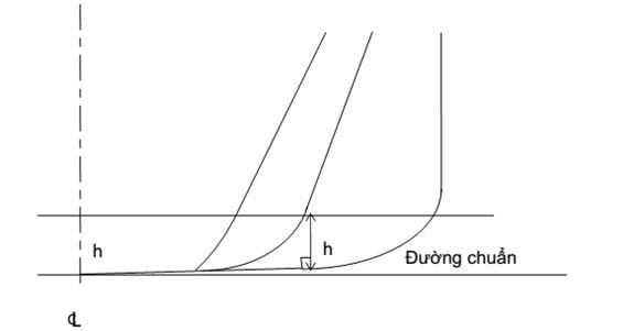
Figure
3.1 Fuel tank boundary lines
6 For ships having an aggregate oil fuel capacity of
600 m3 or more but less than 5,000 m3, oil fuel tanks
shall be located inboard of the moulded line of the side shell plating, nowhere
less than the distance w which, as shown in Figure 3.2, is measured at any
cross-section at right angles to the side shell, as specified below:
w = 0,4 + 2,4C/20.000 (m)
The minimum value of w = 1.0 m;
however for individual tanks with an oil fuel capacity of less than 500 m3
the minimum value is 0.76 m.
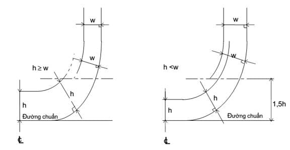
Figure
3.1 Fuel tank boundary lines (bilge area)
7 For ships having a minimum total oil fuel capacity of
5,000 m3, oil fuel tanks shall be located inboard of the moulded
line of the side shell plating, nowhere less than the distance w which, as
shown in Figure 3.2, is measured at any cross-section at right angles to the
side shell, as specified below:
w = 0,5 + C/20.000 (m) or
...
...
...
Hãy đăng nhập hoặc đăng ký Thành viên
Pro tại đây để xem toàn bộ văn bản tiếng Anh.
The minimum value of w = 1,0 (m)
8 Lines of oil fuel piping located at a distance from
the ship’s bottom of less than h, as defined in paragraph 6, or from the ship’s
side less than w, as defined in paragraphs 7 and 8 shall be fitted with valves
or similar closing devices within or immediately adjacent to the oil fuel tank. These valves shall be capable of
being brought into operation from a readily accessible enclosed space the
location of which is accessible from the navigation bridge or propulsion
machinery control position without traversing exposed freeboard or
superstructure decks. These valves shall close in case of remote control system
failure (fail in a closed position) and shall be kept closed at sea at any time
when the tank contains oil fuel except that they may be opened during oil fuel
transfer operations.
(1) Valves of fuel tanks arranged
in accordance with -5, -6, or -7 can be installed in the same manner as suction
wells mentioned under -9 (see Figure 3.2.1);
(2) Valves of fuel tanks whose
position is compliant with -10 can be placed at a position lower than h (as
defined under -5) or w (as defined under -6 or -7) respectively from the bottom
or the side of the ships;
(3) In any case, these valves must
be installed close to fuel tanks.
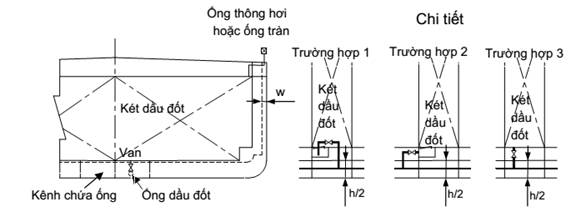
Figure
3.2.1
9 Suction wells in oil fuel tanks may protrude into the
double bottom below the boundary line defined by the distance h provided that
such wells are as small as practicable and the distance between the well bottom
and the bottom shell plating is not less than 0,5 h.
10 Regardless of regulations under -5
to -7, fuel tanks can be placed as far as the edge of the outer hull plate of
the ship if the ship satisfies the accidental oil fuel outflow performance
standard specified below:
...
...
...
Hãy đăng nhập hoặc đăng ký Thành viên
Pro tại đây để xem toàn bộ văn bản tiếng Anh.
OM ≤ 0,0157-1,14.10-6.C for
600 ≤ C < 5.000 (m3)
OM ≤ 0,010 for C ≥ 5.000 (m3)
where:
OM: Mean oil outflow
parameter;
C: Total oil fuel volume, in m3,
at 98% filling.
(2) The following general
assumption shall apply when calculating the mean oil outflow parameter
mentioned in (1).
(a) the ship shall be assumed
loaded to the partial draft (dP ) without trim or heel;
(b) all oil fuel tanks shall be
assumed loaded to 98% of their volumetric capacity;
(c) the nominal density of the oil
fuel (ρn ) shall generally be taken as 1,000 kg/m3. If the density
of the oil fuel is specifically restricted to a lesser value, the lesser value
may be applied;
...
...
...
Hãy đăng nhập hoặc đăng ký Thành viên
Pro tại đây để xem toàn bộ văn bản tiếng Anh.
(3) The following assumptions shall
be used when combining the oil outflow parameters:
(a) The mean oil outflow shall be
calculated independently for side damage and for bottom damage and then
combined into a non-dimensional oil outflow parameter “OM”, as
follows:
OM = (0,4.OMS
+ 0,6.OMB)/C
where:
OMS: mean outflow for
side damage (m3);
OMB: mean outflow for
bottom damage (m3).
(b) For bottom damage, independent
calculations for mean outflow shall be done for 0 m and 2.5 m tide conditions,
and then combined as follows:
OMB = 0,7.OMB(0) + 0,3.OMB(2,5)
where:
...
...
...
Hãy đăng nhập hoặc đăng ký Thành viên
Pro tại đây để xem toàn bộ văn bản tiếng Anh.
OMB(2,5) : mean outflow for minus 2.5 m tide
condition (m3).
(4) The mean outflow for side
damage OMS shall be calculated as follows:
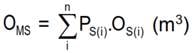
where:
i : each oil fuel tank under
consideration;
n: total number of oil fuel tanks;
PS(i) : the probability of penetrating oil
fuel tank i from side damage, calculated in accordance with (6);
OS(i) : the outflow, in m3, from side damage to oil
fuel tank i, which is assumed equal to the gross tonnage in oil fuel tank i at
98% filling.
(5) The mean outflow for bottom
damage shall be calculated for each tidal condition as follows:
...
...
...
Hãy đăng nhập hoặc đăng ký Thành viên
Pro tại đây để xem toàn bộ văn bản tiếng Anh.
where:
i : each oil fuel tank under
consideration;
n: total number of oil fuel tanks;
PB(i) : the probability of penetrating oil fuel tank i from bottom
damage, calculated in accordance with (7);
OB(i) : the outflow from oil fuel tank i, in m3,
calculated in accordance with (c) and (d);
CDB(i) : factor to account for oil capture as defined in (e).
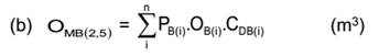
where:
i, n, PB(i) and CDB(i) :
as defined in (a);
...
...
...
Hãy đăng nhập hoặc đăng ký Thành viên
Pro tại đây để xem toàn bộ văn bản tiếng Anh.
(c) The oil outflow OB(i)
for each oil fuel tank shall be calculated based on pressure balance
principles, in accordance with the following assumptions:
(i) The ship shall be assumed
stranded with zero trim and heel, with the stranded draft prior to tidal change
equal to the partial draft dp;
(ii) The oil fuel level after
damage shall be calculated as follows:
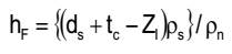
where:
hF : the height of the oil fuel surface above Zl, (m);
tc : the tidal change, in
m. Reductions in tide shall be expressed as negative values;
Zl : the height of the
lowest point in the oil fuel tank above the baseline, (m);
ρs : density of seawater,
to be taken as 1,025 kg/m3;
...
...
...
Hãy đăng nhập hoặc đăng ký Thành viên
Pro tại đây để xem toàn bộ văn bản tiếng Anh.
(d) The oil outflow OB(i)
for any tank bounding the bottom shell plating shall be taken not less than the
following formula, but no more than the tank capacity.
OB(i) = Hw.A
Hw is determined as follows:
(i) Hw =
1,0 (m) when YB = 0;
(ii) Hw = BB/50 but not greater than 0.4 m, when YB
is greater than BB/5 or 11,5 m, whichever is less. Where YB
values outboard BB/5 or 11,5 m, whichever is less, HW is
to be linearly interpolated (see Figure 3.3);
(iii) “Hw” is to be
measured upwards from the midship flat bottom line. In the turn of the bilge
area and at locations without a clearly defined turn of the bilge, Hw
is to be measured from a line parallel to the midship flat bottom, as shown for
distance “h” in Figure 3.1.
YB : the minimum value of YB over the length of the
oil fuel tank, where at any given location, YB is the
A : the maximum horizontal projected
area of the oil fuel tank up to the level of Hw from the bottom of
the tank.
(e) In case of bottom damage, a
portion from the outflow from an oil fuel tank may be captured by non-oil
compartments. This effect is approximated by application of the factor CDB(i)
for each tank, which shall be taken as follows:
...
...
...
Hãy đăng nhập hoặc đăng ký Thành viên
Pro tại đây để xem toàn bộ văn bản tiếng Anh.
CDB(i) = 1,0 for other fuel tanks.
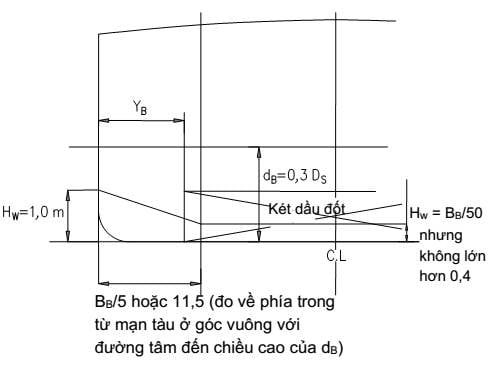
Figure
3.3 Dimensions for calculation of the minimum oil outflow
(6) The probability Ps
of breaching a compartment from side damage shall be calculated as follows:
Ps = PSL .PSV .PST
where:
PSL = 1− PSf − PSa
:
Probability the damage will extend
into the longitudinal zone bounded by Xa and Xf;
PSV = 1− PSu − PSl
:
...
...
...
Hãy đăng nhập hoặc đăng ký Thành viên
Pro tại đây để xem toàn bộ văn bản tiếng Anh.
PST = 1− PSy :
Probability the damage will extend
transversely beyond the boundary defined by y;
PSa, PSf, PSl,
and PSu :
Probabilities below shall be
determined by linear interpolation from the table of probabilities for bottom
damage in Schedule 3.1;
PSa : the probability the damage will lie entirely aft of
location Xa/Lf;
PSf : the probability the damage will lie entirely forward of
location Xf/Lf;
PSl : The probability the damage will lie entirely below the
tank;
PSu : The probability the damage will lie entirely above the
tank;
PSy : The probability the damage will lie entirely outboard the
tank. PSy is determined as follows. However, PSy must not be greater
than 1.
...
...
...
Hãy đăng nhập hoặc đăng ký Thành viên
Pro tại đây để xem toàn bộ văn bản tiếng Anh.
PSy = 0,749
+ {5 − 44,4(y/Bs −
0,05)}(y/BS − 0,05)
for 0,05 < y/BS < 0,1
PSy = 0,888
+ 0,56(y/BS − 0,1)
for y/BS ≥
0,1
Xa : the longitudinal distance from aft terminal of Lf
to the aft most point on the compartment being considered (m);
Xf : the longitudinal distance from aft terminal of Lf
to the foremost point on the compartment being considered (m);
Zl : the vertical distance from the moulded baseline to the
lowest point on the compartment being considered (m). Where Zl is
greater than Ds, Zl shall be taken as Ds;
Zu : the vertical
distance from the moulded baseline to the highest point on the compartment
being considered (m). Where
Zu is greater than Ds, Zu shall be taken as Ds;
y: the minimum horizontal distance
measured at right angles to the centerline between the compartment under
consideration and the side shell (m). Within side bilge area, y is not required
to take into account h section on the basement where h is less than B/10, 3 m
or top of tank.
(7) The probability PB
of breaching a compartment from side damage shall be calculated as follows:
PB = PBL .PBT .PBV
...
...
...
Hãy đăng nhập hoặc đăng ký Thành viên
Pro tại đây để xem toàn bộ văn bản tiếng Anh.
PBL = 1
− PBf − PBa : probability the damage will extend into the longitudinal
zone bounded by Xa and Xf;
PBL = 1
− PBp − PBs : probability the damage will extend into transverse zone
bounded by YP
and YS;
PBV = 1
− PBz : probability the damage will extend vertically above the
boundary defined by z;
PBa, PBf, PBp
and PBs: Probabilities below shall be determined by linear
interpolation from the table of probabilities for bottom damage in Schedule
3.2;
PBa: the probability the damage will
lie entirely aft of location Xa/Lf;
PBf: the probability the damage will
lie entirely forward of location Xf/Lf;
PBp : probability the damage will lie entirely to port of the
tank;
PBs : probability the damage will lie entirely to starboard the
tank;
PBz : probability the damage will lie entirely below the tank. PBz shall be calculated as follows. However, PBs is
not to be taken greater than 1.
...
...
...
Hãy đăng nhập hoặc đăng ký Thành viên
Pro tại đây để xem toàn bộ văn bản tiếng Anh.
Yp : the transverse distance from the port-most point on the
compartment located at or below the waterline dB, to a vertical plane located BB/2
to starboard of the ship’s centerline, (m);
Ys : the transverse distance from the starboard-most point on
the compartment located at or below the waterline dB, to a vertical
plane located BB /2 to starboard of the ship’s centerline, (m);
z: the minimum value of z over the
length of the compartment, where, at any given longitudinal location, z is the
vertical distance from the lower point of the bottom shell at that longitudinal
location to the lower point of the compartment at that longitudinal location
(m);
Xa and Xf as defined in (6).
(8) For the purpose of maintenance
and inspection, any oil fuel tanks that do not border the outer shell plating
shall be located no closer to the bottom shell plating than the minimum value
of h in -5 and no closer to the side shell plating than the applicable minimum
value of w in -6 and -7.
Schedule
3.1 Table of Probabilities for side damage
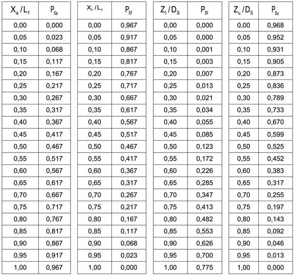
Schedule
3.2 Table of Probabilities for bottom damage
...
...
...
Hãy đăng nhập hoặc đăng ký Thành viên
Pro tại đây để xem toàn bộ văn bản tiếng Anh.
1.2.4 Ship-to-ship oil transfer plan
at sea
1 In respect of oil tankers of a minimum gross tonnage
of 150 participating in cargo transfer between oil tankers at sea, ship-to-ship
oil transfer plan at sea must be available on board. This plan must be presented in
language used by masters and officers of the ships. In respect of ships
operating international voyage, languages other than English used in the plan
must be accompanied by English translation.
2 Cargo transfer must be recorded in oil record books
or other record books deemed appropriate by the VR. This record must be kept on board
for at least 3 years.
3 Ship-to-ship oil transfer plan at sea in -1 must be
appraised by VR and prepared on the basis of:
(1) Part I - Prevention, Manual on
Oil Pollution of IMO;
(2) Oil transfer guidelines between
oil tankers, fourth edition of ICS and OCIMF.
1.2.5 Special requirements for the
use or transfer of oil in the Antarctic Ocean
1 With the exception of ships operating to maintain
safety of other ships or engaging in rescue operations, the following cargo oils
must not be transported in bulk, used as ballast water, or transported and used
as fuel:
(1) Crude oil having density
greater than 900 kg/m3 at 15 oC;
...
...
...
Hãy đăng nhập hoặc đăng ký Thành viên
Pro tại đây để xem toàn bộ văn bản tiếng Anh.
(3) Bitumen, asphalt and emulsion
thereof must not be transported in the Antarctic Ocean (defined under 1.11.7 of
Appendix I). However, where previous activities already include the
transportation or use of any of the aforementioned oil types, washing or washing
of tanks and pipes is not mandatory.
1.2.6 Requirements for the use and
transport of heavy grade oil used as fuel in the Arctic Ocean
1 With the exception of ships maintaining safety of
other ships or engaging in search and rescue and specialized ships responding
to oil spill incidents, oil types under 1.2.5(2) must not be used and
transported to be used as fuel for ships operating in the Arctic Ocean from
July 1 of 2024.
2 Notwithstanding regulations in -1, oil types under
1.2.5(2) must not be used and transported to be used as fuel for ships
operating in the Arctic Ocean from July 1 of 2029 by ships to which 1.2.3 of
this Part or 2.2.1 Part 10 applies.
3 Where activities prior to entering the Arctic Ocean
already involve the use and transportation of oil types under 1.2.5(5) as fuel,
washing or washing of tanks and pipes is not mandatory.
Chapter
2 EQUIPMENT PREVENTING POLLUTION CAUSED BY OIL FROM MACHINERY SPACE
2.1 General provisions
2.1.1 Application requirement
Regulations under this Chapter apply
to structures and equipment preventing pollution caused by oil or oily mixtures
from machinery spaces.
...
...
...
Hãy đăng nhập hoặc đăng ký Thành viên
Pro tại đây để xem toàn bộ văn bản tiếng Anh.
2.2.1 Volume of oil residue tanks
1 Ships with minimum gross tonnage of 400 must be
outfitted with tanks in appropriate storage capacity to contain oil residues. Volume of a tank or tanks must be
greater than the minimum volume under (1) or (2) below.
(1) Minimum volume V1 of tanks on
ships where fuel tanks do not contain ballast water;
V1 = K1 C D
(m3)
where:
K1 = 0,015: For ships
where heavy fuel oil is purified for main engine use;
K1 = 0,005: For ships using diesel oil or heavy fuel oil which
does not require purification.
C: Daily fuel oil consumption
(tonne/day). In which, an engine is deemed main engine (fuel oil
consumption at maximum continuous capacity) and auxiliary engine (fuel oil
consumption of half of all auxiliary engines at maximum continuous capacity).
Number of work hours of engines are calculated as follows:
- For ships operating on
international voyage and unrestricted ships or class II restriction ships: 24
hours;
...
...
...
Hãy đăng nhập hoặc đăng ký Thành viên
Pro tại đây để xem toàn bộ văn bản tiếng Anh.
D: maximum period of voyage between
ports where sludge can be discharged ashore (In the absence of precise data, a
figure of 30 days should be used for ships operating on international voyage, 6
days for ships not operating on international voyage with class II restriction,
and 4 days for ships not operating on international voyage with class III
restriction).
(2) Minimum volume V2 of
tanks in ships where fuel tanks contain ballast water:
V2 = V1 + K2B
(m3)
where:
V1: Tank volume
determined or compliant with (1);
K2 = 0,01: For heavy fuel
oil bunker tanks;
K2 = 0,005: For diesel oil bunker tanks;
B: Capacity of oil fuel tanks
(tonne) that can be used as water ballast tanks.
2 Notwithstanding regulations under -1, where ships
with shipbuilding contracts signed (or in the absence of contracts,
shipbuilding process started) before July 1 of 2010 are outfitted with
homogenizing equipment, residue incinerators, or residue removers approved by
VR, it is permissible to adopt the higher value among the following values as V1:
...
...
...
Hãy đăng nhập hoặc đăng ký Thành viên
Pro tại đây để xem toàn bộ văn bản tiếng Anh.
Where: V1, K1,
C, D are determined under -1(1).
Or:
V1 = 1 (m3):
For ships having capacity from exceeding 400 to less than 4.000;
V1 = 2 (m3):
For ships having total capacity from exceeding 4.000.
2.2.2 Structure of oil residue tank
and pipe system
1 Pipe structure and system of oil residue tanks under
2.2.1 must adhere to requirements (1) through (6):
(1) Openings for human access or
for washing and of appropriate dimensions must be situated at such locations
that each part of the tanks can be easily cleaned;
(2) Appropriate instruments for stripping
and discharging oil residue are required;
(3) Other than standard discharge connections
under 2.2.3 of this Part, pipe connections must not be installed to directly
discharge overboard;
...
...
...
Hãy đăng nhập hoặc đăng ký Thành viên
Pro tại đây để xem toàn bộ văn bản tiếng Anh.
(5) Tanks must be outfitted with
separate pumps to withdraw from oil residue tanks and discharge via methods
detailed under (4);
(6) The tanks must not have their
discharge connection directed at ballast water system, oil-contaminated ballast
water tanks, top of the tanks or oil filters except for cases under (a) and
(b). Ships built before January 1 of 2017 must be outfitted in a manner
compliant with this regulation before the first periodic inspection or after
the aforementioned date.
(a) Tanks can be outfitted with
discharge instruments accompanied by manually operated shut-off valves,
instruments for visual observation of settling water for discharge into
oil-contaminated ballast water tanks or dry suction wells or similar
installation as long as such installation is not directly connected to ballast
discharge pipes;
(b) Discharge pipes of oil residue
tanks and ballast pipes can be merged to joint pipes leading towards standard
discharge connections under 2.2.3; such integration and connection to standard
discharge connections under 2.2.3 must prevent oil residue from entering ballast
water system. Such merger is only acceptable if pipe segments connected to
joint pipes leading to standard discharge connections are outfitted with stop
check valves.
2 Pumps mentioned under -1(5) must satisfy requirements
(1) through (4):
(1) Pumps must not be used for
oil-contaminated ballast water;
(2) Pumps must be of a type
appropriate for discharging oil residue onshore;
(3) Power output of pumps Q must at
least equal the following value. Power output of pumps on ships that do not
operate on international voyage can be 0,5 (m3/h):
...
...
...
Hãy đăng nhập hoặc đăng ký Thành viên
Pro tại đây để xem toàn bộ văn bản tiếng Anh.
V: V1 or V2 as defined under 2.2.1-1.
t = 8 hours.
2.2.3 Standard discharge connection
In order to install pipes of reception
facilities connected to discharge pipes from oil residue tanks in a manner
compliant with 2.2.2 above, standard discharge connection compliant with
Schedule 3.3 is required.
Schedule
3.3 Standard dimensions of standard discharge connections
Details
Requirements
Outer diameter
215 mm
...
...
...
Hãy đăng nhập hoặc đăng ký Thành viên
Pro tại đây để xem toàn bộ văn bản tiếng Anh.
Reasonably proportionate to outer
diameter
Bolt circle diameter
183 mm
Slots in flange
6 holes 22 mm in diameter equidistantly
placed on a bolt circle of the above diameter, slotted to the flange
periphery. The slot width to be 22 mm.
Flange thickness
20 mm
Bolts and nuts: quantity and
diameter
6 sets, each of 20 mm in diameter
...
...
...
Hãy đăng nhập hoặc đăng ký Thành viên
Pro tại đây để xem toàn bộ văn bản tiếng Anh.
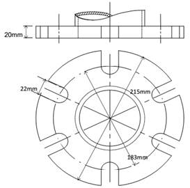
2.3 Oil filters and oil-contaminated
ballast water chest
2.3.1 Oil filter
1 Oil filters must satisfy requirements under (1), (2),
or (3) below and have output compliant with -4 depending on type, dimensions of
the ships and operation area:
(1) Oil filters must be of a type recognized
by the VR under -3 below and ensure that the oil content, while filtering oil
and water mixture, does not exceed 15 ppm;
(2) Oil filters must meet
requirements under (1) and be outfitted with lighting and audible warning
devices of a type recognized by the VR which are automatically activated when
oil content in discharge exceeds 15 ppm or when measurement functionality is
not working as intended;
(3) Oil filters must meet
requirements under (2) and be outfitted with devices that automatically stop
discharging if oil content in discharge exceeds 15 ppm.
2 Pipe system of oil filters must be compatible with pipe
systems of ship as follows:
(1) Oil filters must be appropriate
for use on board and convenient for maintenance;
...
...
...
Hãy đăng nhập hoặc đăng ký Thành viên
Pro tại đây để xem toàn bộ văn bản tiếng Anh.
(3) Placement of sampling locations
between 15 ppm oil filters and 15 ppm alarming devices must ensure that samples
collected truthfully represent water discharged from oil filters in adequate pressure
and flow rate;
(4) Output of feeding pumps (that
feed oil filters) must not exceed 110% nominal output of oil filters, taking
into account both pump dimensions and transmission motors;
(5) System diagram must ensure that
activation interval (including activation time of 15 ppm alarming devices) along
the discharge of oil filters from the moment in which oil content exceeds 15
ppm and moment in which automatic overboard discharge shut-off devices are
automatically activated must be as short as possible and must not be longer
than 20 seconds (for ships having a gross tonnage ≥ 10.000);
(6) Oil filters must be outfitted
with permanent signs that specify all limitations in activation or
installation;
(7) Automatic overboard discharge
shut-off devices in -1(3) must include a valve on discharge pipe exiting 15 ppm
oil filters that automatically changes discharge mode from overboard discharge
to bottom discharge or ballast tank discharge where content of oil in
discharged mixture exceeds 15 ppm (applicable to ships having a gross tonnage ≥
10.000);
(8) Recirculating equipment is
required after automatic shut-off devices and close to overboard discharge
outlets to ensure that oil filters, including 15 ppm alarming devices and
automatic shut-off devices can be tested when overboard discharge valve is
closed (applicable to ships having a gross tonnage ≥ 10.000) (see Figure
3.3.1);
(9) Fail-safe system is required to
prevent overboard discharge in case of centrifuge failure.
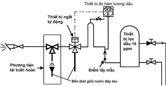
Figure
3.3.1 Placement of recirculating equipment
...
...
...
Hãy đăng nhập hoặc đăng ký Thành viên
Pro tại đây để xem toàn bộ văn bản tiếng Anh.
(1) For ships built or undergoing
major modifications on or after January 1 of 2005: MEPC.107(49);
(2) For ships other than those
under (1) built on or after April 30 of 1994: MEPC.60(33);
(3) For ships other than those
under (1) and (2): A.393(X).
4 Processing output of oil filters (Q, m3/h), generally,
must not be lower than:
(1) Q = 0,00044 x gross tonnage
(for ships having a gross tonnage of les than 1.000);
(2) Q = 0,4 + 0,00004 x gross
tonnage (for ships having a gross tonnage from 1.000 to less than 40.000);
(3) Q = 2 (for ships having a gross
tonnage of at least 40.000).
2.3.2 Oil-contaminated ballast tanks
1 Oil-contaminated ballast tanks on ships compliant
with 2.4.2-2(1) must meet requirements below:
...
...
...
Hãy đăng nhập hoặc đăng ký Thành viên
Pro tại đây để xem toàn bộ văn bản tiếng Anh.
(1) For ships having maximum
continuous rating of main engines less than 1.000 kW
C = 4 (m3)
(2) For ships having maximum
continuous rating of main engines from 1.000 kW to 20.000 kW
C = P/250 (m3)
where:
P : Maximum continuous rating of
main engines (kW).
(3) For ships having maximum
continuous rating of main engines from 20.000 kW
C = 40 + P/250 (m3)
where:
...
...
...
Hãy đăng nhập hoặc đăng ký Thành viên
Pro tại đây để xem toàn bộ văn bản tiếng Anh.
2 Oil-contaminated ballast tanks on ships compliant
with 2.4.2-2(2) must meet requirements below:
Volume of oil-contaminated ballast
tanks (C (m3)) must be equal to or greater than the value determined
using the formula below.
(1) For ships having maximum
continuous rating of main engines less than 1.000 kW
C = 1,5 (m3)
(2) For ships having maximum
continuous rating of main engines from 1.000 kW to 20.000 kW
C = 1,5 + (P - 1000)/1500 (m3)
(3) For ships having maximum
continuous rating of main engines greater than 20.000 kW
C = 14,2+0,2(P-20.000)/1500 (m3)
where:
...
...
...
Hãy đăng nhập hoặc đăng ký Thành viên
Pro tại đây để xem toàn bộ văn bản tiếng Anh.
3 Oil-contaminated ballast tanks on ships compliant
with 2.4.2-2(3) must meet requirements below:
Volume of oil-contaminated ballast
tanks (C (m3)) must be equal to or greater than the value determined
using the formula below.
C = (L/V).Q (m3)
where:
L : Distance of a return trip of the
longest commercial route that the ship has made (nautical mile)
V: Maximum velocity of ships in
long-run tests (nautical mile/hour)
Q = 0,00022 x gross tonnage (GT) of
ships, (m3/h) for ships having GT <1000;
Q = 0,2 + 0,00022 x gross tonnage
(GT) of ships, (m3/h) for ships having GT ≥ 1000.
4 In respect of ships employing such systems that allow
special consideration relating to treatment of oil-contaminated ballast water,
volume of oil-contaminated ballast tanks under -1 and -3 can be reduced.
...
...
...
Hãy đăng nhập hoặc đăng ký Thành viên
Pro tại đây để xem toàn bộ văn bản tiếng Anh.
(1) Oil-contaminated ballast tanks
must be outfitted with devices capable of measuring quantity of ballast water
contaminated with oil;
(2) Tanks must not leak
oil-contaminated ballast water even when ships trim by 10o and heel
by 22,5o;
(3) Placement of oil-contaminated
ballast tanks must allow ballast water to be transported into oil-contaminated
ballast tanks and onshore reception facilities. In this case, the tanks must be
outfitted with standard discharge connection under Schedule 3.3 Article 2.2.3.
2.4 Installation requirements
2.4.1 General provisions
1 Ships having a gross tonnage of at least 400 must be
outfitted with oil filters to treat oil-contaminated ballast water or other oil
in accordance with Schedule 3.4.
2 Ships having a gross tonnage less than 400 must be
outfitted with oil filters under 2.3.1-1(1) where oil-contaminated ballast
water is discharged into the sea.
3 Ships having a gross tonnage less than 400, unless
oil filters under -2 are outfitted, must be outfitted with equipment for
retaining oil or oily mixture on ships to a reasonable extent depending on ship
configuration (for example, oil-contaminated ballast tanks compliant with
2.3.2-2 or 2.3.2-3).
2.4.2 Amendment
...
...
...
Hãy đăng nhập hoặc đăng ký Thành viên
Pro tại đây để xem toàn bộ văn bản tiếng Anh.
2 Notwithstanding regulations under 2.4.1, where ships
mentioned below intend to discharge the entirety of oil-contaminated water into
reception facilities, oil filters can be replaced with oil-contaminated ballast
tanks.
(1) Ships that only operate in
special zones or in Polar Sea;
(2) Ships, such as floating hotels, tankers, etc. usually
anchored, other than unladen repositioning trips.
(3) Ships to which the National
Technical Regulation on classification and construction of sea-going high speed
ships applies, not operating on international voyage or operating on round
trips with defined itinerary of less than 24 hours in duration, including
unladen repositioning trips of these ships.
Schedule
3.4 Regulation on installation of oil filters
Operating zone
Gross tonnage (GT)
GT < 400
400 ≤ GT < 10.000
...
...
...
Hãy đăng nhập hoặc đăng ký Thành viên
Pro tại đây để xem toàn bộ văn bản tiếng Anh.
Ships operating solely in
special zones or in the Arctic.
-*
(II)**
Other than ships mentioned
above
-*
(I)
(II)
Note: The symbols in the schedule denote
the following equipment:
(I): Oil filters mentioned under
2.3.1-1(1).
...
...
...
Hãy đăng nhập hoặc đăng ký Thành viên
Pro tại đây để xem toàn bộ văn bản tiếng Anh.
“-“: No requirement.
*: Where oil-contaminated ballast
water is discharged into the sea, oil filters under 2.3.1-1(1) (see 2.4.1-2)
are required.
**: It is permissible to replace by
equipment for retaining oil-contaminated ballast water.
Chapter
3 STRUCTURE AND EQUIPMENT FOR PREVENTING POLLUTION CAUSED BY OIL TRANSPORTED IN
BULK
3.1 General provisions
3.1.1 Application requirement
1 Provisions under this Chapter apply to structures and
equipment for preventing pollution caused by oil transported in bulk.
2 Provisions under 3.2.4 apply to oil tankers having a
minimum deadweight of 600 tonne as follows:
(1) Ships with construction
contracts signed on or after July 6 of 1993; or
...
...
...
Hãy đăng nhập hoặc đăng ký Thành viên
Pro tại đây để xem toàn bộ văn bản tiếng Anh.
(3) Ships delivered on or after
July 6 of 1996; or
(4) Ships undergoing major
modifications as follows:
(a) Modification contracts are signed
after July 6 of 1993; or
(b) Modification work started after
January 6 of 1994 if modification contracts are not available; or
(c) Modification work finished
after July 6 of 1996.
3 Provisions under 3.2.2-6 and 3.2.2-7 apply to oil
tankers having a minimum deadweight of 5.000 tonne as follows:
(1) Ships with construction
contracts signed on or after February 01 of 1999; or
(2) Ships undergoing construction
process on or after August 1 of 1999 if construction contracts are not
available; or
(3) Ships delivered on or after
February 01 of 2002; or
...
...
...
Hãy đăng nhập hoặc đăng ký Thành viên
Pro tại đây để xem toàn bộ văn bản tiếng Anh.
(a) Modification contracts are signed
after February 01 of 1999; or
(b) Modification work started after
August 01 of 1999 if modification contracts are not available; or
(c) Modification work finished
after February 01 of 2002.
4 Provisions under 3.2.5 apply to
oil tankers having a minimum deadweight of 5.000 tonne and undergoing
construction process on or after January 1 of 2007.
5 Provisions of 3.2.1-1 and 3.3.2-5 apply to oil
tankers as follows:
(1) Ships with construction
contracts signed on or after January 01 of 2007; or
(2) Ships undergoing construction
process on or after July 1 of 2007 if construction contracts are not available;
or
(3) Ships delivered on or after
January 01 of 2010; or
(4) Ships undergoing major
modifications as follows:
...
...
...
Hãy đăng nhập hoặc đăng ký Thành viên
Pro tại đây để xem toàn bộ văn bản tiếng Anh.
(b) Modification work started after
July 01 of 2007 if modification contracts are not available; or
(c) Modification work finished
after January 01 of 2010.
3.2 Hull structure
3.2.1 Placement of bulkhead in cargo
tanks
1 In order to provide adequate protection against oil
pollution in the event of collision or stranding, the following shall be
complied with:
(1) For oil tankers of at least
5.000 tonne in deadweight (DW), the mean oil outflow parameter (OM)
shall be as follows:
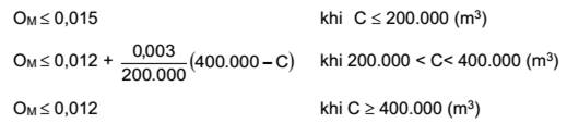
where:
OM: Mean oil outflow
parameter;
...
...
...
Hãy đăng nhập hoặc đăng ký Thành viên
Pro tại đây để xem toàn bộ văn bản tiếng Anh.
(2) Notwithstanding provisions in
(1), in respect of combination carriers between 5,000 tonne of deadweight (DW)
and 200,000 m3 capacity, the mean oil outflow parameter may be applied, provided
calculations are submitted to the satisfaction of the VR, demonstrating that
after accounting for its increased structural strength, the combination carrier
has at least equivalent oil out flow performance to a standard double hull
tanker of the same size having a OM ≤ 0,015.

(3) For oil tankers of less than
5.000 tonne in deadweight (DW), the length of each cargo tank shall not exceed
10 m or one of the following values, whichever is the greater:
(a) Where no longitudinal bulkhead
is installed in cargo tanks:
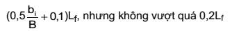
(b) Where a centerline longitudinal
bulkhead is installed inside cargo tanks:
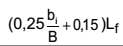
(c) Where two or more longitudinal
bulkheads are installed in cargo tanks:
i) For wing cargo tanks: 0,2Lf
...
...
...
Hãy đăng nhập hoặc đăng ký Thành viên
Pro tại đây để xem toàn bộ văn bản tiếng Anh.
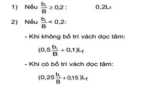
“bi” is the minimum
distance from the ship's side to the outer longitudinal bulkhead of the tank in
question measured inboard at right angles to the centerline at the level
corresponding to the assigned summer freeboard.
(4) The following general
assumption shall apply when calculating the mean oil outflow parameter
mentioned in (1) and (2).
(a) The cargo block length extends
between the forward and aft extremities of all tanks arranged for the carriage
of cargo oil, including slop tanks;
(b) Where this regulation refers to
cargo tanks, it shall be understood to include all cargo tanks, slop tanks and
fuel tanks located within the cargo block length;
(c) The ship shall be assumed
loaded to the load line draft ds without trim or heel. All
calculations mentioned under this regulation depends on draft ds,
even if assigned draft can be greater than ds, such as summer
freeboard;
(d) All cargo oil tanks shall be
assumed loaded to 98% of their volumetric capacity. The nominal density of
cargo oil (ρn) shall be calculated as follows:
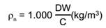
where:
...
...
...
Hãy đăng nhập hoặc đăng ký Thành viên
Pro tại đây để xem toàn bộ văn bản tiếng Anh.
(e) For the purposes of these
outflow calculations, the permeability of each space within the cargo block,
including cargo tanks, ballast tanks and other non-oil spaces shall be taken as
0,99, unless proven otherwise;
(f) Suction wells may be neglected
in the determination of tank location provided that such wells are as small as
practicable and the distance between the well bottom and bottom shell plating
is not less than 0,5h, where h is the height as defined in
3.2.4(1)(a)(ii).
(5) The following assumptions shall
be used when combining the oil outflow parameters:
(a) The mean oil outflow shall be
calculated independently for side damage and for bottom damage and then
combined into a “non-dimensional” oil outflow parameter OM, as
follows:
OM = (0,4.OMS
+ 0,6.OMB)/C
where:
OMS: mean outflow for
side damage (m3);
OMB: mean outflow for
bottom damage (m3).
(b) For bottom damage, independent
calculations for mean outflow shall be done for 0 m and -2,5 m tide conditions,
and then combined as follows:
...
...
...
Hãy đăng nhập hoặc đăng ký Thành viên
Pro tại đây để xem toàn bộ văn bản tiếng Anh.
where:
OMB(0) : mean outflow for
0 m tide condition (m3);
OMB(2,5) : mean outflow
for minus 2.5 m tide condition (m3).
(6) The mean outflow for side
damage shall be calculated as follows:
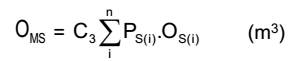
where:
i: each cargo tank under
consideration;
n: total number of cargo tanks;
PS(i) : the probability
of penetrating cargo tank i from side damage, calculated in accordance with
(8);
...
...
...
Hãy đăng nhập hoặc đăng ký Thành viên
Pro tại đây để xem toàn bộ văn bản tiếng Anh.
C3 : 0,77 for ships
having two longitudinal bulkheads inside the cargo tanks, provided these
bulkheads are continuous over the cargo block and Ps(i) is developed
in accordance with this regulation; C3 equals 1,0 for all other
ships or when Ps(i) is developed in accordance with (10).
(7) The mean outflow for bottom
damage shall be calculated for each tidal condition as follows:
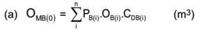
where:
i: each cargo tank under
consideration;
n: total number of cargo tanks;
PB(i) : the probability
of penetrating cargo tank i from bottom damage, calculated in accordance with
(9);
OB(i) : the outflow from
cargo tank i, in m3, calculated in accordance with (c) and (d);
CDB(i) : factor to
account for oil capture as defined in (e).
...
...
...
Hãy đăng nhập hoặc đăng ký Thành viên
Pro tại đây để xem toàn bộ văn bản tiếng Anh.
where:
i, n, PB(i) and CDB(i)
: as defined in (a);
OB(i) : the outflow from
cargo tank i, in m³, after tidal change.
(c) The oil outflow OB(i)
for each cargo tank shall be calculated based on pressure balance principles,
in accordance with the following assumptions:
(i) The ship shall be assumed
stranded with zero trim and heel, with the stranded draft prior to tidal change
equal to the partial draft ds;
(ii) The cargo level after damage
shall be calculated as follows:
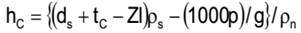
where:
hc : the height of the cargo oil
above Zl, m;
...
...
...
Hãy đăng nhập hoặc đăng ký Thành viên
Pro tại đây để xem toàn bộ văn bản tiếng Anh.
Zl : the height of the lowest point in the cargo tank above
baseline, m;
ρs : density of seawater,
to be taken as 1,025 kg/m3;
p : if an inert gas system is
fitted, the normal overpressure, in kPa, to be taken as not less than 5 kPa; if
an inert gas system is not fitted, the overpressure may be taken as 0;
g : the acceleration of gravity, to
be taken as 9,81 m/s2;
ρn : nominal density of cargo oil, calculated in accordance
with (4)(d).
(d) For cargo tanks bounded by the
bottom shell, unless proven otherwise, oil outflow OB(i) shall be
taken not less than 1% of the total volume of cargo oil loaded in cargo tank i,
to account for initial exchange losses and dynamic effects due to current and
waves.
(e) In case of bottom damage, a
portion from the outflow from a cargo tank may be captured by non-oil
compartments. This effect is approximated by application of the factor CDB(i)
for each tank, which shall be taken as follows:
CDB(i) = 0,6 for cargo
tanks bounded from below by non-oil compartments;
CDB(i) = 1,0 for cargo tanks bounded by the bottom shell.
...
...
...
Hãy đăng nhập hoặc đăng ký Thành viên
Pro tại đây để xem toàn bộ văn bản tiếng Anh.
Ps = PSL .PSV
.PST
PSL = 1− PSf −
PSa : probability the damage will extend into the
longitudinal zone bounded by Xa and
Xf ;
PSV =1− PSu − PSl : probability the damage will extend into the vertical zone
bounded by Zl and Zu ;
PST = 1
− PSy : probability the damage will extend transversely beyond the
boundary defined by y.
PSa , PSf, PSl and PSu : shall be determined by linear interpolation from the table
of probabilities for side damage provided in Schedule 3.5.
PSa : the probability the damage will
lie entirely aft of location Xa/Lf ;
PSf :
the probability the damage will lie entirely forward of location Xf / Lf ;
PSl : the probability the
damage will lie entirely below the tank;
PSu : the probability the
damage will lie entirely above the tank.
...
...
...
Hãy đăng nhập hoặc đăng ký Thành viên
Pro tại đây để xem toàn bộ văn bản tiếng Anh.
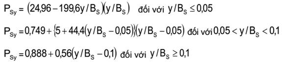
BS : is the greatest moulded breadth of the ship, in meters, at
or below the waterline ds;
Xa : the longitudinal
distance from aft terminal of Lf to the aft most point on the
compartment being considered (m);
Xf : the longitudinal
distance from aft terminal of Lf to the foremost point on the
compartment being considered (m);
Zl : the vertical
distance from the moulded baseline to the lowest point on the compartment being
considered (m);
Zu : the vertical
distance from the moulded baseline to the highest point on the compartment
being considered (m). Zu is
not to be taken greater than DS;
y: the minimum horizontal distance
measured at right angles to the centerline between the compartment under
consideration and the side shell (m).
(9) The probability PB
of breaching a compartment from side damage shall be calculated as follows:
PB = PBL .PBT
.PBV
...
...
...
Hãy đăng nhập hoặc đăng ký Thành viên
Pro tại đây để xem toàn bộ văn bản tiếng Anh.
PBT = 1− PBp −
PBs : probability the damage will extend into the transverse zone
bounded by Yp and Ys ;
PBV = 1 − PBz
: probability the damage will extend vertically above the boundary defined by
z;
PBa, PBf, PBp and PBs : shall be determined by linear interpolation from the table
of probabilities for bottom damage provided in Schedule 3.6
PBa : the probability the
damage will lie entirely aft of location Xa/Lf;
PBf : the probability the
damage will lie entirely forward of location Xf/Lf;
PBp : probability the
damage will lie entirely to port of the tank;
PBs : probability the
damage will lie entirely to starboard the tank.
PBz : the probability the damage will lie entirely below the
tank
PBz is to be calculated as follows. However, PBz is not to be taken
greater than 1.
...
...
...
Hãy đăng nhập hoặc đăng ký Thành viên
Pro tại đây để xem toàn bộ văn bản tiếng Anh.
DS : is the moulded depth, in meters, measured at mid-length to
the upper deck at side;
Xa and Xf are
defined under (8).
Yp :
the transverse distance from the port-most point on the compartment located at
or below the waterline dB, to a vertical plane located BB/2 to
starboard of the ship's centerline, in meters;
Ys : the transverse distance from the starboard-most point on
the compartment located at or below the waterline dB, to a vertical plane
located BB/2 to starboard of the ship's centerline, in meters;
z: the minimum value of z over the
length of the compartment, where, at any given longitudinal location, z is the
vertical distance from the lower point of the bottom shell at that longitudinal
location to the lower point of the compartment at that longitudinal location,
in meters.
(10) Calculation of provisions
under (4) through (9) above uses a simplified probabilistic approach where a
summation is carried out over the contributions to the mean outflow from each
cargo tank. For certain designs such as those characterized by the occurrence
of steps/recesses in bulkheads/decks and for sloping bulkheads and/or a
pronounced hull curvature, more rigorous calculations may be appropriate.
(11) Provisions below regarding
relevant piping arrangements shall apply:
(a) Lines of piping that run
through cargo tanks in a position less than 0.30Bs from the ship's
side or less than 0.30Ds from the ship's bottom shall be fitted with valves or
similar closing devices at the point at which they open into any cargo tank. These
valves shall be kept closed at sea at any time when the tanks contain cargo
oil, except that they may be opened only for cargo transfer needed for
essential cargo operations;
(b) Credit for reducing oil outflow
through the use of an emergency rapid cargo transfer system or other system
arranged to mitigate oil outflow in the event of an accident may be taken into
account only after the effectiveness and safety aspects of the system are
approved by the VR.
...
...
...
Hãy đăng nhập hoặc đăng ký Thành viên
Pro tại đây để xem toàn bộ văn bản tiếng Anh.
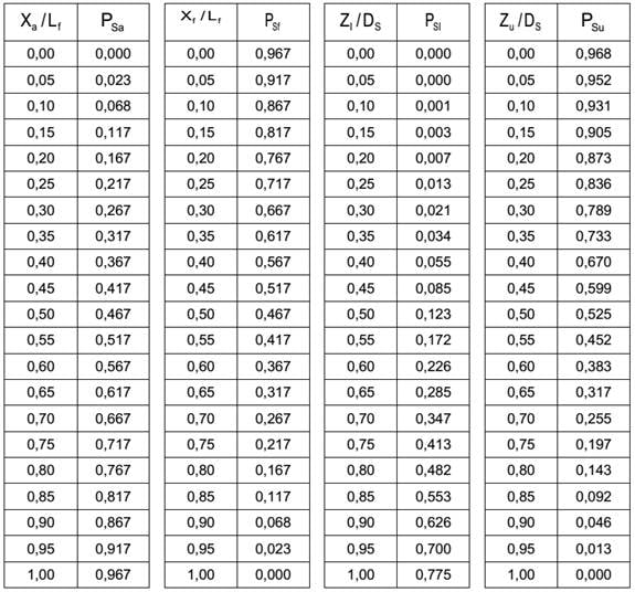
Schedule
3.6 Probability of bottom damage
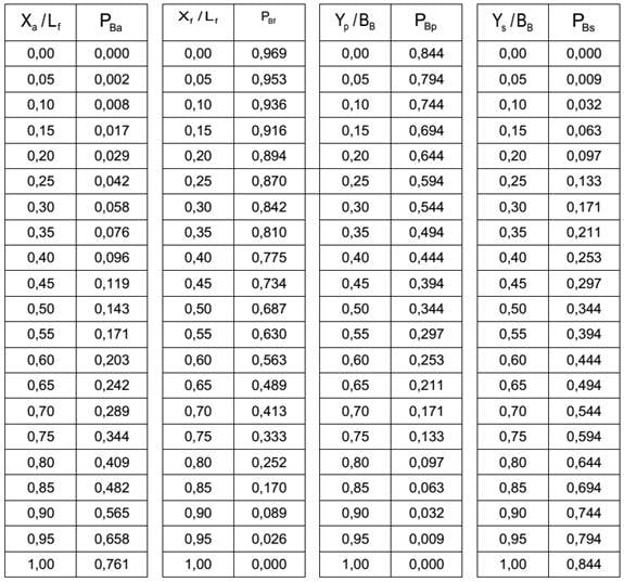
2 In respect of cargo tanks of oil tankers not
regulated by -1, gasket of oilproof materials must be installed in a way where
the hypothetical outflow and dimensional limits of each cargo tank do not
exceed values determined below:
(1) For the purpose of calculating
hypothetical oil outflow from oil tankers, three dimensions of the extent of
damage of a parallelepiped on the side and bottom of the ship are assumed as
follows in accordance with Schedule 3.7 and Schedule 3.8.
Schedule
3.7 Level of side damage
Extent
Level
of damage
...
...
...
Hãy đăng nhập hoặc đăng ký Thành viên
Pro tại đây để xem toàn bộ văn bản tiếng Anh.
 or 14,5 meters, whichever is less
Transverse extent (tc)
B/5 or 11,5 m, whichever is
less (inboard from the ship's side at right
Vertical extent (vc)
From the base line upwards without
limit.
Schedule
3.8 Level of bottom damage
Extent
Level of damage
For 0,3Lf from the forward
perpendicular of the ship
...
...
...
Hãy đăng nhập hoặc đăng ký Thành viên
Pro tại đây để xem toàn bộ văn bản tiếng Anh.
Longitudinal extent (ls)
Lf /10
Lf/10 or 5 m,
whichever is less
Transverse extent (ts)
B/6 or 10 m, whichever is less
but not less than 5 m
5 m
Vertical extent (Vs)
B/15 or 6 m, whichever is less
from the base line.
(2) The hypothetical outflow of oil
in the case of side damage (Oc) and bottom damage (Os)
shall be calculated by the following formulae with respect to compartments
breached by damage to all conceivable locations along the length of the ship to
the extent as defined in (1).
...
...
...
Hãy đăng nhập hoặc đăng ký Thành viên
Pro tại đây để xem toàn bộ văn bản tiếng Anh.
(i) For side damage:
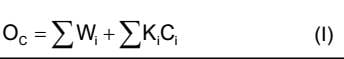
(ii) For bottom damage:
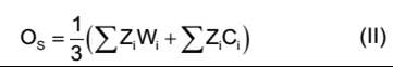
In these case where bottom damage
simultaneously involves four centre tanks, the value of Os may be
calculated according to the formula:
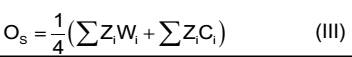
where:
Wi : volume of a wing tank in m3 assumed to be
breached by the damage as specified in (1); Wi for a segregated
ballast tank may be taken equal to zero;
Ci : volume of a centre
tank in m3 assumed to be breached by the damage as specified in (1);
Ci for a segregated ballast tank may be taken equal to zero;
...
...
...
Hãy đăng nhập hoặc đăng ký Thành viên
Pro tại đây để xem toàn bộ văn bản tiếng Anh.
When bi is equal to or
greater than tc, Ki shall be taken equal to zero.
Zi = 1− hi / vs
When bi is equal to or
greater than vs, zi shall be taken equal to zero.
bi : width of wing tank in m under consideration measured
inboard from the ship's side at right angles to the centerline at the level
corresponding to the assigned summer freeboard;
hi : minimum depth of the double bottom in m under
consideration; where no double bottom is fitted hi shall be taken equal to
zero.
(b) If a void space or segregated
ballast tank of a length less than lc as defined in (1) is
located between wing oil tanks, Oc in formula (I) under (a)(i) may
be calculated on the basis of volume Wi being the actual volume of
one such tank (where they are of equal capacity) or the smaller of the two
tanks (if they differ in capacity) adjacent to such space, multiplied by Si
as defined below and taking for all other wing tanks involved in such collision
the value of the actual full volume:
Si = 1− li / lc
where:
li : length in meters of void space or segregated
ballast tank under consideration.
...
...
...
Hãy đăng nhập hoặc đăng ký Thành viên
Pro tại đây để xem toàn bộ văn bản tiếng Anh.
(i) Credit shall only be given in
respect of double bottom tanks which are either empty or carrying clean water
when cargo is carried in the tanks above;
(ii) Where the double bottom does
not extend for the full length and width of the tank involved, the double
bottom is considered non-existent and the volume of the tanks above the area of
the bottom damage shall be included in formula (II) or (iii) under (a)(ii) even
if the tank is not considered breached because of the installation of such a
partial double bottom;
(iii) Suction wells may be
neglected in the determination of the value hi provided such wells
are not excessive in area and extend below the tank for a minimum distance and
in no case more than half the height of the double bottom. If the depth of such
a well exceeds half the height of the double bottom, hi shall be taken equal to
the double bottom height minus the well height. Piping serving such wells if
installed within the double bottom shall be fitted with valves or other closing
arrangements located at the point of connection to the tank served to prevent
oil outflow in the event of damage to the piping. Such piping shall be
installed as high from the bottom shell as possible.
(3) Cargo tanks of oil tankers
shall be of such size and arrangements that the hypothetical outflow Oc
or Os calculated in accordance with the provisions of (2) anywhere
in the length of the ship does not exceed 30,000 m3 or 400  , whichever is the
greater, but subject to a maximum of 40,000 m3. However, where
equipment capable of moving oil from breached tanks or fuel tanks to segregated
ballast tanks or cargo tanks with significant ullage is installed and such
cargo tanks are outfitted with high emergency suction equipment, formula (III)
under (2) may be applied.
, whichever is the
greater, but subject to a maximum of 40,000 m3. However, where
equipment capable of moving oil from breached tanks or fuel tanks to segregated
ballast tanks or cargo tanks with significant ullage is installed and such
cargo tanks are outfitted with high emergency suction equipment, formula (III)
under (2) may be applied.
Such equipment must be capable of
moving oil quantity equivalent to half the volume of the largest tanks among
the breached tanks for 2 hours of operation and the receiving ballast tanks or
cargo tanks must be capable of receiving such oil quantity. Piping serving high
emergency suction equipment must be installed at a height greater than vertical
distance of location of bottom damage.
(4) Individual cargo tanks must not
exceed the following dimensions:
(a) Volume of a wing cargo tank in
oil tanker must not exceed 75% the hypothetical outflow mentioned under (3).
Volume of a center cargo tank must not exceed 50.000 m3. However,
where oil tankers are outfitted with segregated ballast tanks under 3.2.3,
permissible volume of wing cargo tanks located between segregated ballast
tanks, the length of each of which exceeds lc, can be
increased up to the upper limit of the hypothetical outflow as long as width of
wing tanks exceeds tc;
(b) The length of each cargo tank
must not exceed 10 m or any of the following value, whichever is greater:
(i) where no longitudinal bulkhead
is installed inside the cargo tank:
...
...
...
Hãy đăng nhập hoặc đăng ký Thành viên
Pro tại đây để xem toàn bộ văn bản tiếng Anh.
but not to exceed 0,2 Lf
(ii) Where a centerline
longitudinal bulkhead is installed inside the cargo tank:
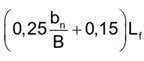
(iii) Where two or more
longitudinal bulkheads are installed inside the cargo tank:
1) For wing tanks: 0,2 Lf
2) For center cargo tanks:
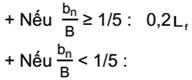
Where no centerline longitudinal
bulkhead is installed:
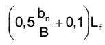
...
...
...
Hãy đăng nhập hoặc đăng ký Thành viên
Pro tại đây để xem toàn bộ văn bản tiếng Anh.
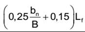
“bn” is the minimum
distance from the ship's side to the outer longitudinal bulkhead of the tank in
question measured inboard at right angles to the centerline at the level
corresponding to the assigned summer freeboard.
(5) In order not to exceed the
volume limits established by (3) and (4) and irrespective of the accepted type
of cargo transfer system installed, when such system interconnects two or more
cargo tanks, valves or other similar closing devices shall be provided for
separating the tanks from each other;
(6) Lines of piping which run
through cargo tanks in a position less than tc from the ship's side or less
than vs from the ship's bottom shall be fitted with valves or
similar closing devices at the point at which they open into any cargo tank.
These valves and closing devices must conform to requirements (i) and (ii)
below. Each valve in branching suction pipe (valves marked with “*1” in Figure
3.3.2) generally must be installed in each open compartment (inside each tank)
(with the exceptions detailed under Figure 3.3.3). However, where placement and
installation of the valves deemed equivalent to the aforementioned requirement
are implemented to prevent further spread of outflow caused by breach of cargo
tanks, the valves marked with “*2” in Figure 3.3.2 may be outfitted inside
adjacent tanks. Where a valve is installed inside adjacent tanks, the valve
must be installed towards the longitudinal bulkhead side of a line that creates
a 45o angle with the bottom.
(i) For the purpose of restricting
the hypothetical outflow and stabilizing incidents, such installation
requirement applies even when valve is not required to prevent acceleration of
outflow;
(ii) Valves are not required in
respective tanks in examples 1 and 2 below:
Example 1: Where pipe passes through
tanks outside of the damage radius (Figure 3.3.3).
Example 2: In case arrangement
depicted under Figure 3.3.4 is used in ore-bulk-oil combination carrier, where
durability and thickness of pipe segments penetrating the bulkhead equal those
of the bulkhead and the length is of minimum according to valve installation
requirement (Figure 3.3.4).
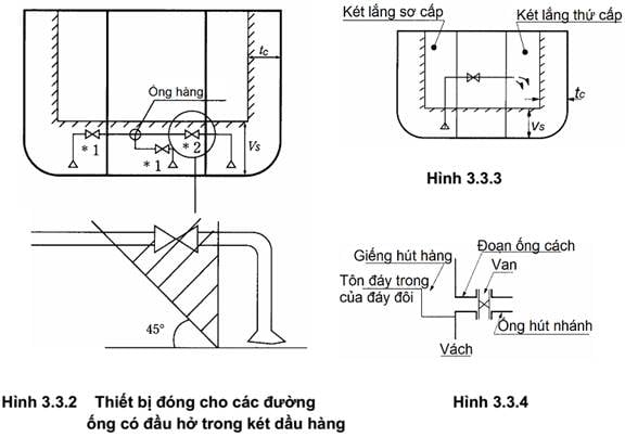
...
...
...
Hãy đăng nhập hoặc đăng ký Thành viên
Pro tại đây để xem toàn bộ văn bản tiếng Anh.
1 All oil tankers must meet subdivision and damage
stability requirements under 3.2.2-3 after the assumed side or bottom damage as
specified in 3.2.2-2, for any operating draft reflecting actual partial or full
load conditions consistent with trim and strength of the ship as well as
relative densities of the cargo. Such damage shall be applied to all conceivable locations
along the length of the ships as detailed under (1) through (3) below:
(1) in tankers of more than 225 m
in length: anywhere in the ship's length;
(2) in tankers of more than 150 meters,
but not exceeding 225 m in length: anywhere in the ship's length except
involving either after or forward bulkhead bounding the machinery space located
aft. Machinery space shall be treated as a single floodable compartment;
(3) in tankers not exceeding 150 m
in length: anywhere in the ship's length between adjacent transverse bulkheads
with the exception of the machinery space. For tankers of 100 meters or less in
length where all requirements of 3.2.2-3 cannot be fulfilled without materially
impairing the operational qualities of the ship, VR may allow relaxations from
these requirements. Ballast conditions where the tanker is not carrying oil in
cargo tanks, excluding any oil residues, shall not be considered.
2 The following provisions regarding the extent and
characteristics of the assumed damage shall apply:
(1) Side damage extent under
Schedule 3.9;
(2) Bottom damage extent under Schedule
3.10. However, in respect of oil tankers with minimum deadweight of 20.000
tonne, the assumed damage under Schedule 3.10 must be complemented by assumed
damage to bottom shell plating in accordance with Schedule 3.11;
(3) If any damage of a lesser
extent than the maximum extent of damage specified in (1) and (2) would result
in a more severe condition, such damage shall be considered;
(4) Where the damage involving
transverse bulkheads is envisaged as specified in 3.2.2-1(1), transverse
watertight bulkheads shall be spaced at least at a distance equal to the
longitudinal extent of assumed damage specified in (1) in order to be
considered effective. Where transverse bulkheads are spaced at a lesser
distance, one or more of these bulkheads within such extent of damage shall be
assumed as non-existent for the purpose of determining flooded compartments;
...
...
...
Hãy đăng nhập hoặc đăng ký Thành viên
Pro tại đây để xem toàn bộ văn bản tiếng Anh.
(a) the spacing of the adjacent
bulkheads is less than the longitudinal extent of assumed damage specified in
(1); or
(b) there is a step or recess in a
transverse bulkhead of more than 3,05 m in length, located within the extent of
penetration of assumed damage. In this provision, the step formed by the after
peak bulkhead and after peak top shall not be regarded as a step for the
purpose of requirement under 3.3.2.
(6) If pipes, ducts or tunnels are
situated within the assumed extent of damage, arrangements shall be made so
that progressive flooding cannot thereby extend to compartments other than
those assumed to be floodable for each case of damage.
3 Oil tankers shall be regarded as complying with the
damage stability criteria if the requirements under (1) through (5) are met:
(1) The final waterline, taking
into account sinkage, heel and trim, shall be below the lower edge of any
opening through which progressive flooding may take place. Such openings shall
include air-pipes and those which are closed by means of weathertight doors or
hatch covers and may exclude those openings closed by means of watertight
manhole covers and flush scuttles, small watertight cargo tank hatch covers
which maintain the high integrity of the deck, remotely operated watertight
sliding doors, and sidescuttles of the non-opening type;
(2) In the final stage of flooding,
the angle of heel due to unsymmetrical flooding shall not exceed 25o,
provided that this angle may be increased up to 30o if no deck edge
immersion occurs;
(3) The stability in the final
stage of flooding shall be investigated and may be regarded as sufficient if
the righting lever curve has at least a range of 20o beyond the
position of equilibrium in association with a maximum residual righting lever
of at least 0,1 m within the 20o range; the area under the curve
within this range shall not be less than 0,0175 m radians. Unprotected openings
shall not be immersed within this range unless the space concerned is assumed
to be flooded. Within this range, the immersion of any of the openings listed
in (1) and other openings capable of being closed watertight may be approved by
VR;
(4) The stability must be sufficient
during intermediate stages of flooding;
(5) Equalization arrangements
requiring mechanical aids such as valves or cross-levelling pipes, if fitted,
shall not be considered for the purpose of reducing an angle of heel or
attaining the minimum range of residual stability to meet the requirements of
(1) through (3) and sufficient residual stability shall be maintained during
all stages where equalization is used. Spaces which are linked by ducts of a
large cross-sectional area may be considered to be common.
...
...
...
Hãy đăng nhập hoặc đăng ký Thành viên
Pro tại đây để xem toàn bộ văn bản tiếng Anh.
Extent
Level
of damage
Longitudinal extent
1/3 Lf 2/3
or 14,5 m, whichever is less
Transverse extent
B/5 or 11,5 m, whichever is less
(inboard from the ship's side at right angles to the centerline at the level
corresponding to the assigned summer freeboard)
Vertical extent
From the base line upwards without
limit.
Schedule
3.10 Level of bottom damage
...
...
...
Hãy đăng nhập hoặc đăng ký Thành viên
Pro tại đây để xem toàn bộ văn bản tiếng Anh.
Level
of damage
For 0,3 Lf from the
forward perpendicular of the ship
Any other part of the ship
Longitudinal extent
1/3 Lf 2/3
or 14,5 m, whichever is less
1/3 Lf 2/3
or 5 m, whichever is less
Transverse extent
B/6 or 10 m, whichever is less
B/6 or 5 m, whichever is less
...
...
...
Hãy đăng nhập hoặc đăng ký Thành viên
Pro tại đây để xem toàn bộ văn bản tiếng Anh.
B/15 or 6 m, whichever is less
from the base line
4 The requirements of -1 above shall be confirmed by
calculations which take into consideration the design characteristics of the
ship, the arrangements, configuration and contents of the damaged compartments;
and the distribution, relative densities and the free surface effect of
liquids. The
calculations shall be based on provisions (1) through (5) below:
(1) Account shall be taken of any
empty or partially filled tank, the relative density of cargoes carried, as
well as any outflow of liquids from damaged compartments;
(2) Permeabilities must be assumed
in the same manner as depicted under Schedule 3.12;
Schedule
3.11 Level of bottom damage
Extent
Level
of damage
Longitudinal extent
Ships of 75.000 tonnes deadweight
and above: 0,6 Lf measured from the forward perpendicular
...
...
...
Hãy đăng nhập hoặc đăng ký Thành viên
Pro tại đây để xem toàn bộ văn bản tiếng Anh.
Transverse extent
B/3 anywhere in the bottom
Vertical extent
Breach of the outer hull
Schedule
3.12 Permeabilities
Spaces
Permeabilities
Appropriated to stores
0,60
...
...
...
Hãy đăng nhập hoặc đăng ký Thành viên
Pro tại đây để xem toàn bộ văn bản tiếng Anh.
0,95
Occupied by machinery
0,85
Voids
0,95
Intended for consumable liquids
0 -
0,95*
Intended for other liquids
0 -
0,95*
...
...
...
Hãy đăng nhập hoặc đăng ký Thành viên
Pro tại đây để xem toàn bộ văn bản tiếng Anh.
* : Permeabilities of a partially flooded
space must depend on the amount of liquid occupied said space. In case of
damage to any liquid tank, it is assumed that all liquid in that tank will be
replaced by saltwater up to the last stable surface.
(3) The buoyancy of any
superstructure directly above the side damage should be disregarded. The
unflooded parts of superstructures beyond the extent of damage, however, may be
taken into consideration provided that they are separated from the damaged
space by watertight divisions and the requirements of 3.2.2-3(1) in respect of
these intact spaces are complied with. Hinged watertight doors can be accepted
as watertight divisions in the superstructures;
(4) The effect of free surfaces
shall be taken into account at an angle of 5o for individual divisions.
VR may request or permit free surface correction determined at an angle greater
than 5o in respect of partially flooded tanks;
(5) For the purpose of calculating
clear surface effects of consumable liquid, it should be assumed that for each
type of liquid at least one transverse pair or a single centerline tank has a
free surface and the tank or combination of tanks taken into account should be
those where the effect of free surfaces is the greatest.
5 All oil tanker adopting regulations under this Part
shall be outfitted in accordance with requirements under (1) and (2) below:
(1) Information pertaining to cargo
handling and distribution satisfies provisions under 3.2.2; and
(2) Data pertaining to ship’s
ability to meet damage stability conforms to 3.2.2, including results of
exemptions permitted under 3.2.2-1(3).
6 Oil tankers of at least 5,000 tonnes deadweight must
meet intact stability below in the most unfavorable conditions of cargo and
ballast during transport of liquid cargo. Liquid cargo transport mentioned under -6 and -7 includes
activities transporting liquid cargo implemented on board such as
filling/removing cargo, relocating cargo, ballasting/de-ballasting, relocating
ballast water, and washing tank. However, this does not include asymmetrical
ballasting/cargo loading if the ship is outfitted with longitudinal partitions,
all tanks on one side are empty while all tanks on the other side are
partially/completely full.
(1) While at sea, requirements
under 2.2.1 of Part 10 Section II of National Technical Regulation on
classification and construction of sea-going steel ships must be met;
...
...
...
Hãy đăng nhập hoặc đăng ký Thành viên
Pro tại đây để xem toàn bộ văn bản tiếng Anh.
7 In respect of general cargo ships of at least 5,000 tonnes
deadweight, in respect of fulfilling requirements under -6, information on
intact stability during liquid cargo handling shall be included in stability
notice which is appraised by VR and posted at cargo pump control rooms and fed
into stability instrument (if equipped)
8 All oil tankers shall be outfitted with stability
instruments which can inspect conformance with standards on intact and damage
stability, are deemed by VR compliant with standards issued by IMO under
documents below:
(1) Chapter 4, Part B of MSC.267(85):
International Code on Intact Stability, 2008 (IS Code, 2008);
(2) Part 4, Appendix of
MSC.1/Circ.1229: Guidelines for the approval of stability instruments; (3)
Technical standards under Part 1 of MSC.1/Circ.1461: Guidelines for
verification of damage stability requirements for tankers.
9 Notwithstanding requirements under -8, stability
instruments of ship built before January 1 of 2016 are not required to be
replaced if they can inspect conformance with standards on intact and damage
stability in a manner satisfactory to VR’s requirements. Ships built before January 1 of 2016
must meet requirements under -8 at the initial inspection for certification or
before January 1 of 2021 at the latest.
10 Where stability instruments
installed on board conform to requirements under -8 and -9, VR-appraised
documents of stability instruments shall be stored on board.
11 VR may consider exemption from
requirements under -8 through -10 for ships mentioned below as long as
procedures for determining intact and damage stability are able to meet
equivalent safety level when the ships are loaded to approved state.
(1) Specialized ships with limited
changes in load so that all expected loads have been appraised in stability
notice sent to the masters and outfitted in accordance with requirements under
-5;
(2) Ships of which stability is
determined remotely via instruments approved by the VR;
...
...
...
Hãy đăng nhập hoặc đăng ký Thành viên
Pro tại đây để xem toàn bộ văn bản tiếng Anh.
(4) Ships built before January 1 of
2016 whose appraised KG/KM meets all requirements pertaining to intact and
damage stability.
3.2.3 Segregated ballast tank
All crude oil tankers of at least
20.000 tonnes deadweight and oil-product tankers of at least 30.000 tonnes
deadweight shall be outfitted with segregated ballast tanks, the volume and
arrangement of which shall be as follows: However, provisions in (2) below are
not mandatory when adopting 3.2.4:
(1) Volume of all segregated
ballast tanks in ballasted state, including light ship weight and segregated
ballast so that draft and trim meet all provisions under (a) through (c) below.
However, oil tankers with length Lf below 150 m at segregated ballast state are
only required to meet requirements under (d).
(a) Theoretical midship draft (dm)
in meter (excluding ship deformation) shall not be lower than:
2,0 + 0,02 Lf
(b) Draft at forward and after
perpendiculars shall correspond to values determined by midship draft (dm) as
mentioned in (a) if aft trim is not greater than 0,015L; and
c) In any case, trim draft at after
perpendiculars shall not be lower than trim required to entirely submerge the
rudders;
(d) Average minimum draft
(m) ≥ 1,550 + 0,023Lf and the highest maximum longitudinal trim (m)
≤ 1,600+0,013Lf.
...
...
...
Hãy đăng nhập hoặc đăng ký Thành viên
Pro tại đây để xem toàn bộ văn bản tiếng Anh.
(a) Segregated ballast tanks and
other closed compartments other than cargo oil tanks within the length of cargo
oil tanks (Lt) shall be arranged in a away that regulations below
are met:
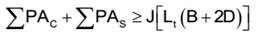
where:
PAC: Side shell plating in m2 of individual segregated ballast
tank or compartments that are not cargo oil tanks, using calculated dimensions;
PAS: Bottom shell plating in m2 for individual tank or compartment, using calculated
dimensions;
Lt : The length between the front end of cargo tanks, (m);
D: Theoretical height shall be
measured vertically from the upper edge of the bottom girders to the upper edge
of girders of freeboard at amidships, in meter. In respect of ships with
rounded board edge, theoretical height shall be measured to intersections of
theoretical board projections and theoretical side shell plating projections,
projections that go through board edges that are parts of corner elements;
J: J = 0,45 for oil tankers with
20.000 tonnes deadweight;
J = 0,30 for oil tankers with at
least 200.000 tonnes deadweight, taking into accounts requirements under (b)
hereof.
...
...
...
Hãy đăng nhập hoặc đăng ký Thành viên
Pro tại đây để xem toàn bộ văn bản tiếng Anh.
(b) In respect of oil tankers with
at least 200.000 tonnes deadweight, J can be decreased as follows:

where:
a = 0,25 for oil tankers with
200.000 tonnes deadweight;
a = 0,40 for oil tankers with
300.000 tonnes deadweight;
a = 0,50 for oil tankers with at
least 420.000 tonnes deadweight.
In respect of ships whose weight
falls in-between prescribed values, the value of a shall be determined via
interpolation.
OC and OS : Values mentioned under 3.2.1(2);
OA :
Amount of oil run-off allowed under 3.2.1(3).
...
...
...
Hãy đăng nhập hoặc đăng ký Thành viên
Pro tại đây để xem toàn bộ văn bản tiếng Anh.
(i) Width of a partially full side
tanks, side tanks whose height starts from other enclosed compartments or deck
to the top of double bottom or to other enclosed compartments shall not be
lower than 2 m. Width of side tanks or other enclosed compartments shall be
measured on the inside from the ship board and perpendicular to the centerline
of the ship. Side tanks or other enclosed compartments whose minimum width is
lower than 2 m shall not be included for the purpose of determining PAC;
(ii) Minimum vertical height of
individual double bottom tanks or other enclosed compartments shall not be
lower than B/15 or 2 m, whichever is lower. Double bottom tanks or other
enclosed compartments whose minimum height is lower than the aforementioned
value shall not be included for the purpose of determining PAS.
Minimum width and minimum height of side tanks or double bottom tanks shall be
measured outside of the bottom of the ship and, in case of minimum width,
outside of the bilge shell area.
3.2.4 Prevention of oil pollution in
case of collision or running aground
(1) All oil tankers having at least
5.000 tonnes deadweight must meet any provisions from (a) through (c) below:
(a) Cargo tanks shall be protected
by ballast tanks or spaces that are not cargo tanks and fuel tanks throughout
their length as follows:
(i) Side tanks or compartments
shall be continuous throughout the height of ship board or from the upper side
of double bottoms to the upper deck, excluding the bilge shell side, if any. All
tanks in this compartment shall recede from theoretical lines of side shell
plating by a distance w according to Figure 3.4. The value of w, measured at
any cross section perpendicular to side shell plating, shall be as follows:
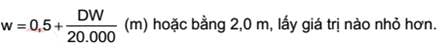
However, minimum value of w = 1 m.
(ii) Regardless of cross section,
height of each double bottom tanks or compartments shall be determined so that
the distance h between the bottom of cargo tanks and theoretical lines of
bottom shell platings which is measured perpendicular from bottom shell
platings according to Figure 3.4 is not lower than:
...
...
...
Hãy đăng nhập hoặc đăng ký Thành viên
Pro tại đây để xem toàn bộ văn bản tiếng Anh.
However, minimum value of h = 1 m.
(iii) Where the values of h and w
are different at bilge area or areas without clearly defined bilges at the
bottom of the ship, the value of w shall be prioritized from a position that is
greater than 1,5 h above the moulded baseline according to Figure 3.4.
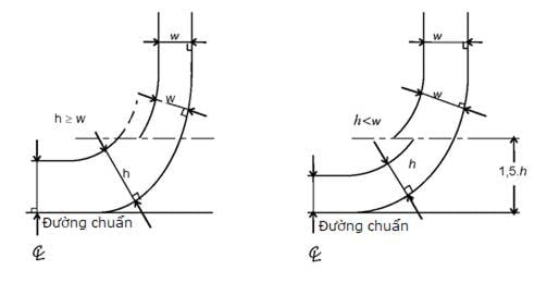
Figure
3.4 Required width of double bottoms and double shells
(iv) In respect of crude oil
tankers with at least 20.000 tonnes deadweight and oil product tankers with at
least 30.000 tonnes deadweight, total volume of side tanks, double bottom
tanks, fore tanks, and aft tanks shall not be lower than volume of segregated
ballast tanks necessary to meet 3.2.3(1). Side tanks or side areas and double
bottom tanks meeting provisions under 3.2.3(1) shall be so arranged as
identical along the length of cargo tanks as possible. Additional segregated
ballast tanks for relieving general bending stress of ship hull, trim, etc. can
be located anywhere in the ships.
(v) Suction wells in cargo tanks
may protrude into double bottoms below moulded baseline by a distance of h as
long as these wells are as small as possible and distance between the bottom of
the wells and bottom shell plating is not lower than 0,5 h.
(vi) Ballast tanks and other tanks
such as measurement pipes, ventilation pipes of ballast tanks must not
penetrate cargo tanks. Cargo pipes and similar pipes serving cargo tanks must
not penetrate ballast tanks. Exemption of these regulations shall be acceptable
for short pipes as long as they are welded tight or otherwise sealed tight via
similar methods.
(b) Cargo tanks shall be protected
by deck platings, ballast tanks or compartments that are not cargo storage
compartments and fuel tanks throughout their length as follows:
(i) Cargo and gas pressure applying
to bottom shell plating and creating a boundary between the cargo and seawater
must not be greater than hydrostatic pressure of seawater outside as depicted
using the formula below:
...
...
...
Hãy đăng nhập hoặc đăng ký Thành viên
Pro tại đây để xem toàn bộ văn bản tiếng Anh.
where:
hc : Height of cargo making contact with bottom shell plating
(m);
ρc : Highest density of cargo (tonne/m3);
dn : Lowest draft while loading (m);
ρs : Density of seawater (tonne/m3);
∆p : Highest installation pressure of pressure
valve/vacuum valve of cargo tank (bar);
f : Safety factor = 1,1;
g: Gravitational acceleration (9,81
m/s2).
(ii) Any transverse partitions
necessary to meet aforementioned regulations shall be located at a height not
lower than B/6 or 6 m, whichever is lower and not greater than 0,6D above
mounded baseline where D represents theoretical midship height.
...
...
...
Hãy đăng nhập hoặc đăng ký Thành viên
Pro tại đây để xem toàn bộ văn bản tiếng Anh.
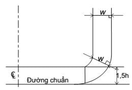
Figure
3.5 Required width of double shell
(iv) Crude oil tankers with at
least 20.000 tonnes deadweight and oil product tankers with at least 30.000 tonnes
deadweight, total volume of side tanks, fore tanks, and aft tanks must meet
provisions under 3.2.4(1)(a)(iv).
(v) Ballast water pipes and cargo
pipes must meet provisions under 3.2.4(1)(a)(vi).
(c) Other oil tanker design and
structure solutions can be accepted by VR as equivalent substitute for
provisions under 3.2.4(1)(a) as long as these solutions offer at least equal
oil contamination protection in case of collision or running aground.
(2) Oil tankers with less than
5.000 tonnes deadweight must meet provisions (a) and (b) below:
(a) Double bottom tanks or double
bottom compartments compliant with 3.2.4(1)(a)(ii) shall be located throughout
the length of cargo tank lines. In this case, h under 3.2.4(1)(a)(ii) can be
determined using formula below:
h = B/15 (m)
However, in respect of minimum value
of h = 0,76 m at bilge area of side shell and areas with non-clearly defined
bilge areas, the lines surrounding cargo tanks shall be parallel with midship
plane according to Figure 3.6.
...
...
...
Hãy đăng nhập hoặc đăng ký Thành viên
Pro tại đây để xem toàn bộ văn bản tiếng Anh.
Figure
3.6 Required height of double bottom
(b) Volume of each cargo tanks
shall not be greater than 700 m3 unless side tanks or side spaces compliant
with 3.2.4(1)(a)(i) are located along the length of cargo tank. In this case, w
under 3.2.4(1)(a)(ii) can be determined using formula below:
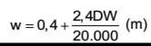
The minimum value of w = 0,76 m
(3) Notwithstanding regulations
under 3.1.1-2, in respect of oil tankers of at least 500 in volume operating in
international voyage and built on or after September 1 of 1984, oil shall not
be contained in any compartment before collision bulkheads installed in
accordance with 11.1.1-1 Part 2A Section II of the National Technical
Regulation on classification and construction of sea-going steel ships. Oil
tankers other than those mentioned above are not allowed to contain oil in any
compartment before cross section perpendicular to ship centerline where
collision bulkheads are assumed to have been installed in accordance with the
aforementioned regulations.
3.2.5 Cargo pump room protection
1 Cargo pump rooms on oil tankers with at least 5.000
tonne in deadweight shall be provided with a double bottom such that at any
cross-section the depth of each double bottom tank or space shall be such that
the distance h between the bottom of the pump-room and the ship’s base line
measured at right angles to the ship’s base line is not less than specified
below:
h = B/15 (m) or
h = 2,0 (m), whichever is smaller.
...
...
...
Hãy đăng nhập hoặc đăng ký Thành viên
Pro tại đây để xem toàn bộ văn bản tiếng Anh.
2 In case of pump rooms whose bottom plate is located
above the base line by at least the minimum height required in paragraph -1
above (e.g. gondola stern designs), there will be no need for a double bottom
construction in way of the pump-room.
3 Ballast pumps, if provided in pump rooms, shall be
provided with suitable arrangements to ensure efficient suction from double
bottom tanks.
4 Notwithstanding the provisions under -1 and -2 above,
where the flooding of the pump-room would not render the ballast or cargo
pumping system inoperative, a double bottom need not be fitted.
5 Collection traps can be located deep in double
bottoms if these traps are realistically small; the height from the bottom of
collection traps to ship baselines is not lower than 0,5 h.
3.3 Equipment and pipe arrangement
3.3.1 Shipboard oil storage system
1 Oil tankers with at least 150 in total volume shall
be outfitted with appropriate cargo tank washing system.
2 Oil tankers with less than 150 in total volume shall
be outfitted with slop storage system which discharges into reception
facilities. However,
where oil discharge system installed on board is satisfactory to requirements
under 3.3.2, this regulation is not mandatory.
3 Oil tankers with at least 150 in total volume shall
be outfitted with at least one slop tank of adequate volume to store tank
washings, oil residues and dirty ballast residues in a manner that satisfies
provisions under 3.3.1-4 through 3.3.1-9 below. Oil tankers greater than 70.000
tonnes deadweight shall be outfitted with at least 2 slop tanks. Total volume of slop tanks, other
than cases detailed under (1) through (3), shall not be lower than 3% oil
storage volume of the ship:
...
...
...
Hãy đăng nhập hoặc đăng ký Thành viên
Pro tại đây để xem toàn bộ văn bản tiếng Anh.
(2) Total volume of slop tanks of
oil tankers outfitted with segregated ballast tanks satisfactory to 3.2.3 or
oil tankers outfitted with COW system satisfactory to 3.4 shall not be lower
than 2%;
However, where washing water
collected in a slop tank or slop tanks is sufficient to be used to clean
another tank without additional water required and where eductors, tank washing
system providing sufficient water for eductors are installed, total volume of
slop tanks can be reduced to a minimum of 1,5%.
(3) Total volume of slop tanks of
general cargo ships on which cargo oil is contained in tanks with smooth walls
shall not be lower than 1%;
However, where washing water
collected in a slop tank or slop tanks is sufficient to be used to clean another
tank without additional water required and where eductors, tank washing system
providing sufficient water for eductors are installed, total volume of slop
tanks can be reduced to a minimum of 0,8%.
4 Slop tanks shall be so designed particularly in respect
of the position of inlets, outlets, baffles or weirs where fitted, so as to
avoid excessive turbulence and entrainment of oil or emulsion with the water.
5 Adequate equipment for washing cargo tanks and
transported contaminated ballast water and washing water from cargo tanks to
slop tanks shall be provided.
6 Slop tanks shall be outfitted with oil discharge
monitoring and control systems for residues of ballast water and washing water
of which characteristics are detailed under (1) through (6) below and deemed
compliant with (7) below by VR.
(1) A recording device is
integrated with the system for providing a continuous record of the discharge
in liters per nautical mile and total quantity discharged, or the oil content
and rate of discharge;
(2) The record in (1) shall be
identifiable as to time and date;
...
...
...
Hãy đăng nhập hoặc đăng ký Thành viên
Pro tại đây để xem toàn bộ văn bản tiếng Anh.
(4) Oil discharge monitoring and
control systems shall be outfitted with alarms that provide visual and audible
warnings where discharge rate exceeds 30 liters per nautical mile or where
total quantity of oil discharged into the sea exceeds 1/30.000 of total
quantity of the particular cargo of which the residue formed a part or where
oil discharge monitoring and control systems are damaged. Total quantity of the
particular cargo relates to the total quantity of the particular cargo which
was carried on the previous voyage and should not be construed as relating only
to the total quantity of cargo which was contained in the cargo tanks into
which water ballast was subsequently loaded;
(5) Discharge of any oily mixture
shall be automatically suspended when alarm goes off. However, in respect of
ships with less than 4.000 tonnes deadweight and built before January 1 of
2005, this requirement can be exempted;
(6) Other manual operating scheme
must be present and functional in case of damaged oil discharge monitoring and
control systems;
(7) Oil discharge monitoring and
control systems for residues of ballast water and washing water shall meet the
following standards:
(a) For ships built on or after
January 1 of 2005: MEPC.108(49);
(b) For ships intended for the
transport of biofuel mixture containing at least 75% of fossil fuel and built
on or after January 1 of 2005: MEPC.240(65), unless otherwise stipulated by VR;
(c) For ships other than those
under (a) and (b) above built on or after October 2 of 1986: A. 586(14);
(d) For ships other those under (a)
through (c): A. 496(XII) and MEPC.13(19).
7 In order to ensure compliance with requirements under
(1) through (5) below of oil discharge monitoring and control systems, pipeline
arrangement shall be:
...
...
...
Hãy đăng nhập hoặc đăng ký Thành viên
Pro tại đây để xem toàn bộ văn bản tiếng Anh.
(a) The system shall be outfitted
with valves next to sampling sensors. Where sensors are installed in cargo
pipes, 2 consecutive valves shall be installed in sampling pipes. Either of these
valves can be a remotely-controlled sampling valve;
(b) Sampling sensors shall be so
positioned to be easily removed and preferably at accessible locations on
vertical discharge pipes. Where sampling sensors are installed on horizontal
discharge pipes, these sensors shall be installed on pipes through which liquid
always travels at all time during discharge process. All sampling sensors
usually penetrate into discharge pipes by 1/4 of the pipes;
(c) Washing sensors and pipe system
shall be facilitated by fixed water washing system or equivalent solutions;
(d) Total interval between a change
to delivered mixture and a corresponding change to measurement reading shall be
as short as possible and shall not be longer than 40 seconds which already
include response time of measurement instruments;
(e) Arrangement of washing
discharge shall facilitate test run, calibration of oil content meters, and
reset configuration if needed;
(f) Valves allowing manual sampling
from pipes to measurement instruments below in flow direction of sampling pumps
or similar locations shall be installed.
(2) Sampled water returned to slop
tanks must not flow freely into the tanks. In respect of bulk cargo tankers
outfitted with inert gas system, airtight segments in an U shape with
sufficient height shall be installed on pipes leading to slop tanks;
(3) Flow rate meters for measuring
discharge rate shall be installed in vertical discharge pipes or other
appropriate discharge pipes so that the flow rate meters are always submerged
during discharge;
(4) Flow rate meters shall be so
designed to measure all possible flow velocity in normal operating conditions.
It is possible to employ other arrangement such as 2 flow rate meters of
different measurement ranges;
...
...
...
Hãy đăng nhập hoặc đăng ký Thành viên
Pro tại đây để xem toàn bộ văn bản tiếng Anh.
8 Other effective oil/water interface detectors
approved for compliant with MEPC.5(XIII) by the VR shall be employed to effectively define
separation between oil/water in slop tanks or other tanks from where residues
are discharged directly to the sea.
9 Ships shall be outfitted with instruction manuals for
oil discharge monitoring and control systems for residues of ballast water and
washing water. Such
instruction manuals shall be appraised by the VR, including all necessary costs
for operating and maintaining the systems and include details below. These
details can be grouped as below or in similar manner:
(1) Introduction: Primary
parameters of ship, installation date of the system, list of remaining content
of the instruction manual. Full details of Regulation 31, 34 of Appendix I
MARPOL;
(2) Part 1: Instructions pertaining
to equipment of manufactures for primary elements of the system. Such
instructions include installation, test operation, operation and remediation
procedures for oil content supervision instruments;
(3) Part 2: Operating instructions
including description of cargo ballasting system, side discharge pipes with
sampling points, regular operating procedures, input for automatic operation,
input for manual operation (if any) of locks and discharge valve control (if
applicable), override system, visual and audible warning, recorded output
parameters, requirement for manual input configuration, flow rate during
discharge via gravity, and deballasting pump. Instructions for discharging
oil-contaminated water shall be provided in case of equipment failure.
Information above shall be depicted in copies of appropriate diagrams; Reference
to part 1 above is permissible if necessary;
(4) Part 3 Technical instructions
including incident discovery program, maintenance logs, hydraulic graphs,
compressed air graphs, electricity graphs, and system-wide presentation. Reference
to part 1 above is permissible if necessary;
(5) Part 4: Test and examination
procedures include function test areas during installation and instructions on
which registration personnel rely on for initial examination and during
operation. Reference to part 1 above is permissible if necessary;
(6) Appendix 1: Technical
characteristics of the system, including location and installation of parts,
equipment for maintaining intactness of “safety” areas, safety requirements of
electrical equipment in dangerous areas and copies of appraised drawings,
placement of sampling pipes, sampling delay, design and arrangement of sampling
sensors, discharge washing and configuration reset system. Reference to part 1
above is permissible if necessary;
(7) Appendix 2: Copies of
certificate of type approval and certificate of manufacturing process of
primary parts.
...
...
...
Hãy đăng nhập hoặc đăng ký Thành viên
Pro tại đây để xem toàn bộ văn bản tiếng Anh.
11 In respect of oil tankers operating
on domestic voyage and at most 50 nautical miles away from the nearest land,
regulations under 3.3.1-6 through 3.3.1-9 do not apply if VR deem such
exemption is appropriate and if oil tankers only discharge into reception
facilities. In this
case, discharge of oil tankers must be recorded in oil record books.
3.3.2 Oil discharge system
1 In every oil tanker, a discharge manifold for
connection to reception facilities for the discharge of dirty ballast water or
oil-contaminated water shall be located on the open deck on both sides of the
ship.
2 In every oil tanker, a discharge manifold for
discharging ballast water or oil-contaminated water in cargo compartments to
the sea shall be led to the open deck or to the ship's side above the waterline
in the deepest ballast condition. Unless such discharge can be implemented via other discharge
manifolds in cases (1) or (2) below. However, in respect of oil tankers to be
built under contracts on or after October 1 of 2007, the discharge shall take
place above the waterline in the deepest ballast condition:
(1) Discharge manifold for
discharging segregated ballast water and clean ballast water if instruments are
available for examining surface of segregated ballast water immediately before
discharge and if discharge is implemented at ports or offshore terminals via
gravity or via pumps at sea where the ballast water exchange is performed via
methods approved by the VR;
(2) Discharge manifold for
discharging segregated ballast water and clean ballast water if oil/water
interface detectors capable of examining ballast water immediately before
discharge according to 3.3.1-8 and if discharge at sea is performed by gravity.
However, even in this situation, discharge manifolds for discharging from slop
tanks shall be led to open deck or to the ship's side above the waterline in
the deepest ballast condition.
3 Means for stopping the discharge into the sea from a
position on the upper deck or above located so that the manifold in use
mentioned under 3.3.2-1 and the discharge to the sea from the pipelines
mentioned under 3.3.2-2 may be visually observed. Means for stopping the
discharge need not be provided at the observation position if a positive communication
system such as a telephone or radio system is provided between the observation
position and the discharge control position.
4 In addition to regulations under 3.3.2-1 through
3.3.2-3, crude oil tankers of 20.000 tonnes deadweight and above and oil product
tankers of 30.000 tonnes deadweight and above shall be outfitted with discharge
system detailed under (1) and (2):
(1) Oil piping so designed and
installed that oil retention in the lines is minimized shall be equipped;
...
...
...
Hãy đăng nhập hoặc đăng ký Thành viên
Pro tại đây để xem toàn bộ văn bản tiếng Anh.
5 Where oil tankers of at least 150 in total gross
tonnage are outfitted with sea chests connected to cargo oil lines permanently, shall be equipped
with both a sea chest valve and an inboard isolation valve. In addition to
these valves, the sea chest shall be capable of isolation from the cargo piping
system whilst the tanker is loading, transporting or discharging cargo by use
of a positive means. Such a positive means a facility that is installed in the
pipeline system in order to prevent, under all circumstances, the section of
pipeline between the sea chest valve and the inboard valve being filled with
cargo.
3.4 Crude oil washing system
3.4.1 Regulations regarding
installation
1 Crude oil tankers of 20.000 tonnes deadweight and
above shall be outfitted as follows:
(1) COW system satisfactory to 3.4;
(2) Inert gas system satisfactory
to National Technical Regulation on classification and construction of
sea-going steel ships for cargo tanks and slop tanks;
(3) Manuals of procedures and
systems detailing COW system and operating procedures approved by VR.
2 Oil tankers other than those under -1 above and
outfitted with COW system shall meet regulations under 3.4, except for
3.4.3-1(2), 3.4.4-1(2) through (5) and 3.4.5-1(2), (4), (6), and (7).
3.4.2 Piping of COW system
...
...
...
Hãy đăng nhập hoặc đăng ký Thành viên
Pro tại đây để xem toàn bộ văn bản tiếng Anh.
(1) COW pipes and valves in supply
pipe system shall be of steel or equivalent materials with sufficient strength
to withstand the highest working pressure and shall be connected and braced
accordingly;
(2) COW pipes shall be secured and
independent from firefighting pipes or pipes other than COW pipes. However, a
part of cargo pipes onboard can be used in junction with COW pipes if such
operation is approved by VR;
In respect of general cargo ships
carrying non-liquid cargo, COW pipes shall be of a type that can be
disassembled when necessary as long as they are airtight upon re-assembly for
use;
Where tank washing equipment must be
available and mounted to cargo tank lids, flexible pipes connecting COW system
with tank washing equipment shall be used and shall be of a flanged type
approved by VR. Pipe length must not exceed the length necessary for connecting
tank washing equipment to an enclosed position outside of tank lid. A separate
storage units for the flexible pipes shall be required.
(3) Supply pipes for tank washing
shall be outfitted with means for preventing overpressure. Oil overflowing
through safety means installed to prevent overpressure shall be carried to
suction inlets of supply pumps;
(4) Where tank washing system is
outfitted with a water supply valve for water washing, such valve shall have
sufficient strength; where the risk of crude oil infiltrating washing system is
present, a means for closing and opening connected apparatus shall be provided
and joined using flanges;
(5) Where manometers or other
instruments are installed on pipe system, a shut-off valve shall be installed
close to such instruments or such instruments shall be designed to be airtight;
(6) All elements of COW system must
be located outside of machinery space. Where steam heaters are equipped to
assist tank washing system, such heaters shall be effectively shut off by
double block valves discharge connection that have been clearly marked;
(7) Where a supply pipe is used for
both crude oil and washing water, such pipe shall be so designed to discharge
oil to slop tanks or other cargo tanks as much as possible prior to water
washing;
...
...
...
Hãy đăng nhập hoặc đăng ký Thành viên
Pro tại đây để xem toàn bộ văn bản tiếng Anh.
(9) Supply pipes of COW system
shall be secured to ship shell at appropriate locations and be so installed to
accommodate thermal expansion and conform to the shape of ship shell. Means for
securing supply pipes shall be so designed to dissipate hydraulic shock without
displacing the pipes in any significant manner. Where the pipes are secured
must be as far as possible from where crude oil is fed into pipes. Where a tank
washing equipment is used for securing pipe branches, special means for securing
said pipe sections shall be equipped where tank washing equipment is
disassembled.
3.4.3 COW equipment
1 COW equipment shall satisfy provisions (1) through
(7) below:
(1) COW equipment of tanks shall be
firmly secured and designed in a manner is approved by VR;
(2) Technical performance
characteristics of tank washing equipment shall be determined by diameter of
hoses, working pressure, operating methods and cycles. Performance
characteristics of stand-alone tank washing equipment shall allow the equipment
to effectively wash these cargo tanks during the period clearly defined under
equipment and operational manuals;
(3) Tank washing equipment shall be
located in individual cargo tanks and be so installed and mounted to meet
requirements of VR. Where tank washing equipment is installed at positions that
are significantly low below the deck due to protrusion of tank structures,
installation of special brackets for tank washing equipment and supply pipes
shall be taken into consideration;
(4) Stand-alone tank washing
equipment shall be able to be shut off by block valves installed on supply
pipes. Where tank washing equipment installed on deck is detached regardless of
reasons, solutions for shutting off pipes carrying oil to the equipment shall
be implemented if the equipment is detached. Similarly, an appropriate means
for closing cargo tanks in form of metal sheets or other appropriate means
approved by VR shall be equipped;
(5) Where transmission parts are
not integrated with tank washing equipment, tank washing equipment shall be
provided in adequate quantity so that any tank washing equipment does not have
to be moved away from its installation location 3 times or more to perform tank
washing schedule under equipment and operational manuals;
(6) Quantity and location of tank
washing equipment shall be so determined that all vertical and horizontal
surfaces can be washed directly or effectively via reflected streams. For the
purpose of evaluating effectiveness of reflected streams, special attention
shall be paid to washing of overhead horizontal surfaces and the following
parameters:
...
...
...
Hãy đăng nhập hoặc đăng ký Thành viên
Pro tại đây để xem toàn bộ văn bản tiếng Anh.
(b) In respect of vertical surfaces
of side shells of tanks, total area of surface at which direct stream is
obstructed by decks, bottom girders, primary girders, longitudinal girders, or
other major hull structure elements shall not exceed 15% total area of side
shells of tanks. Special attention shall be paid to whether a minimum of 2 tank
washing equipment is required to achieve adequate tank washing result depending
on arrangement of structure elements in the tanks.
(7) Structure of tank washing
equipment attached to decks shall be so designed t accommodate means for
indicating rotational speed and motion of equipment outside of cargo tanks.
3.4.4 COW pumps
1 Pumps delivering crude oil to tank washing equipment
shall meet provisions (1) through (5) below:
(1) Pumps delivering crude oil to
tank washing equipment shall be cargo oil pumps or pumps equipped specifically
for this purpose;
(2) Pump capacity shall be so
determined to allow the highest number of tank washing equipment under
equipment and operational manuals to operate at pre-determined pressure and
discharge rate. Where eductors are equipped, the pumps shall be capable of
providing driving fluid for eductors in a manner that satisfies 3.4.5-1(2);
(3) Pump capacity shall be so
determined to satisfy provision under (2) in the event of failure of a pump.
Placement of pumps and pipes shall be so determined to allow COW system to
perform all functions in the event of failure of a pump;
(4) The system shall be capable of
washing tanks using crude oil even when two or more cargo types are being
carried onboard;
(5) Measures shall be taken to
allow washing equipment to maintain pressure under (2) to effectively perform
COW even when pressure that is present at shore reception facilities is lower
than pressure necessary for COW. This requirement must be met even in case of
failure of a pump. The minimum pressure necessary for COW shall be defined in
equipment and operational manuals.
...
...
...
Hãy đăng nhập hoặc đăng ký Thành viên
Pro tại đây để xem toàn bộ văn bản tiếng Anh.
1 Stripping system shall satisfy provisions (1) through
(7) below:
(1) Design of systems for stripping
crude oil at the bottom of cargo tanks shall meet all requirements imposed by
the VR;
(2) Design and capacity of
stripping system shall be so determined to strip all oil and residues from the
bottom of the tanks;
(3) Capacity of stripping system
shall be so determined to satisfy 1,25 times total discharge amount if all
simultaneously operating tank washing equipment where tank washing is being conducted
as per equipment and operational manuals;
(4) For the purpose of inspecting
dryness of cargo tanks following COW, means such as liquid gauges, manual
measuring instruments, and measuring instruments for verifying operating
conditions of stripping system in (6) shall be provided. Unless an accepted
means is installed to effectively verify whether tank bottom is dry, an
appropriate means shall be provided to facilitate physical inspection at the
furthermost section of cargo tanks and 3 other appropriate positions. The term
“dry” implies that areas adjacent to dry suction inlets only contain a small
amount of oil while other areas in general are dry;
(5) For the purpose of stripping
oil from cargo tanks, pumps of volume, self-priming centrifugal pumps,
eductors, or other pumps satisfactory to VR’s requirements shall be used. Where
stripping pipes are connected to multiple tanks, means for isolating tanks that
are not being stripped shall be provided;
(6) A monitoring system shall be
provided to monitor effectiveness of stripping system. The monitoring equipment
shall be located in cargo control rooms at safe, accessible locations from
which stationing personnel can observe and indicate via remote instruments. Where
stripping pumps are provided, a rate meter or a flow meter or a flow velocity
meter and a pressure gauge or other equivalent instruments shall be installed
at connection to discharge pipes. Where eductors are provided, pressure gauges
shall be provided at suction inlets and outlets of drive fluid of eductors;
combined measuring instruments shall be provided at suction inlets of eductors
to function as inspecting instruments;
(7) Structures inside tanks must be
so arranged that oil gutters of stripping system to suction wells of tanks are
satisfactory to (2) and (4).
3.4.6 Placement of segregated
ballast tanks
...
...
...
Hãy đăng nhập hoặc đăng ký Thành viên
Pro tại đây để xem toàn bộ văn bản tiếng Anh.
Chapter
4 REGULATIONS FOR TRANSITION PERIOD
4.1 General provisions
4.1.1 Application requirement
1 Provisions under this Chapter applies to structures
and equipment for preventing pollution caused by oil in ships built before
August 25, 1983 unless otherwise specified under -3 and -4 below.
2 Ships regulated by this Chapter must meet
requirements under Chapter 1, Chapter 2, and Chapter 3 according to Schedule
3.13.
3 Oil tankers of 5.000 tonnes deadweight and above,
built or laid keel or delivered before the time limit under 3.1.1-2 must
satisfy 4.3.10. However, these regulations are not mandatory for:
(1) Oil tankers satisfactory to
3.2.4;
(2) Oil tankers satisfactory to
3.2.4(1)(a)(i) and (ii) or 3.2.4(1)(b)(i), (ii), and (iii) or 3.2.4(1)(c). In
this case, separation distance for side shells and bottom shells must satisfy
to corresponding regulations under 2.6.1(2) of Part 8E Section II of the
National Technical Regulation on classification and construction of sea-going
steel ships and 3.2.3(2)(c)(ii).
4 Oil tankers, other than those under -3(2), of 600 tonnes
deadweight and above carrying heavy grade oil shall meet provisions under
4.3.11 in addition to provisions under 4.3.10 regardless of when the ships are delivered.
However, these
regulations may not be mandatory for oil tankers operating on national voyages
or used as floating storage units of heavy grade oil on sea waters under
Vietnamese sovereignty.
...
...
...
Hãy đăng nhập hoặc đăng ký Thành viên
Pro tại đây để xem toàn bộ văn bản tiếng Anh.
1 In this Chapter, the definitions below have their
meaning attributed to them as follows:
(1) Ships that are not oil tankers
(a) “Ship N” means a ship that:
(i) Is built under contracts signed
after December 31, 1975 or has its keel laid after June 30, 1976; or
(ii) Is delivered after December
31, 1979; or
(iii) Undergoes major modification
as seen in:
1) Modification contracts are signed
after December 31, 1975; or
2) Modification work started after
June 30, 1976; or
3) Modification work finished after
December 31, 1979.
...
...
...
Hãy đăng nhập hoặc đăng ký Thành viên
Pro tại đây để xem toàn bộ văn bản tiếng Anh.
(2) Oil tankers
(a) “Ship NN” means a ship that
falls under any of the cases below:
(i) The ship is built under
contracts signed after December 31, 1975 or has its keel laid after June 30,
1976; or
(ii) The ship is delivered after
June 1, 1982; or
(iii) The ship undergoes major
modification as seen in:
1) Modification contracts are signed
after June 01, 1982; or
2) Modification work started after
January 01, 1980; or
3) Modification work finished after
June 01, 1982.
(b) “Ship EN” means a ship that
falls under any of the case below:
...
...
...
Hãy đăng nhập hoặc đăng ký Thành viên
Pro tại đây để xem toàn bộ văn bản tiếng Anh.
(ii) The ship has its keel laid
between June 30, 1976 and January 1, 1980; or
(iii) The ship is delivered between
December 31, 1979 and June 1, 1982; or
(iv) The ship undergoes major
modification as seen in:
1) Modification contracts are signed
between December 31, 1975 and June 1, 1979; or
2) Modification work started between
June 30, 1976 and January 1, 1980; or
3) Modification work finished
between December 31, 1979 and June 1, 1982.
(c) “EE ship” means a ship that is
not “NN ship” or “EN ship”.
(3) “New ship” means “N ship”, “NN
ship”, and “EN ship”;
(4) “Existing ship” means “ship E”
and “EE ship”;
...
...
...
Hãy đăng nhập hoặc đăng ký Thành viên
Pro tại đây để xem toàn bộ văn bản tiếng Anh.
(a) Modification that significantly
alters size or weight capacity of the ship; or
(b) Modification that alters ship
type; or
(c) Modification is performed for
the purpose of extending useful life of the ship according to VR’s
recommendation; or
(d) Modification that alters other
details in a manner that causes a new ship to adopt appropriate regulations of
Part 1 except for existing ship.
(6) “Heavy-duty diesel oil” means
diesel oil for use in maritime and of which composition differs where at least
50% of the hydrocarbon fractions (by volume) distil at most 340 oC
during tests approved by the VR;
(7) “FO oil” means heavy
hydrocarbon fractions collected or residue of crude oil or mixture of these
ingredients to be used as fuel for heat or energy of which characteristics are
equivalent to technical properties approved by the VR;
(8) “Heavy grade oil” means:
(a) Crude oil whose density at 15 oC
is greater than 900 kg/m3;
(b) Oil other than crude oil whose
density at 15 oC is greater than 900 kg/m3 or kinematic
viscosity at 50 oC is greater than 180 mm2/s;
...
...
...
Hãy đăng nhập hoặc đăng ký Thành viên
Pro tại đây để xem toàn bộ văn bản tiếng Anh.
(9) “Category 1 oil tanker” means
an oil tanker of 20.000 tonnes deadweight and above for carrying crude oil, FO,
heavy-duty diesel oil, or lubricants or ship of 30.000 tonnes deadweight and
above for carrying oil other than the aforementioned oil, these ships do not
qualify as NN ship;
(9) “Category 2 oil tanker” means
an oil tanker of 20.000 tonnes deadweight and above for carrying crude oil, FO,
heavy-duty diesel oil, or lubricants as cargo or ship of 30.000 tonnes
deadweight and above for carrying oil other than the aforementioned oil, these
ships qualify as NN ship. However, oil tankers of 20.000 to less than 30.000 tonnes
deadweight satisfactory to 3.2.3(1) and 3.2.3(2) shall be considered “category
2 oil tanker” otherwise “category 1 oil tanker”;
(11) “Category 3 oil tanker” means
an oil tanker of 5.000 tonnes deadweight and above that does not meet
deadweight requirement of (9) and (10).
4.2 General requirements
4.2.1 Fore side tank arrangement
Regulations under 1.2.1-1 apply to
ships whose construction contracts are signed after January 1, 1982 or construction
process started after July 1, 1982 in respect of ships of a gross tonnage of
400 or more, N ship, EN ship, and NN ship.
Schedule
3.13 Application of Chapter 1, 2, and 3 to ships defined under 4.1.1-1
×:
Applicable; ○: Not applicable; ─ : Beyond scope of application
...
...
...
Hãy đăng nhập hoặc đăng ký Thành viên
Pro tại đây để xem toàn bộ văn bản tiếng Anh.
Oil
tanker
N
ship
E
ship
NN
ship
EN
ship
EE
ship
Chapter 1
General provisions
1.1.1
...
...
...
Hãy đăng nhập hoặc đăng ký Thành viên
Pro tại đây để xem toàn bộ văn bản tiếng Anh.
×
×
×
×
1.1.2
×
○
×
○
...
...
...
Hãy đăng nhập hoặc đăng ký Thành viên
Pro tại đây để xem toàn bộ văn bản tiếng Anh.
1.2.1-1
1.2.1-2
1.2.1-3
×
×
×
○
○
×
...
...
...
Hãy đăng nhập hoặc đăng ký Thành viên
Pro tại đây để xem toàn bộ văn bản tiếng Anh.
×
×
○
×
×
○
○
×
Chapter 2
...
...
...
Hãy đăng nhập hoặc đăng ký Thành viên
Pro tại đây để xem toàn bộ văn bản tiếng Anh.
2.2.1-1
×
×
×
×
×
(1) and (2) of 2.2.1-1
×
○
...
...
...
Hãy đăng nhập hoặc đăng ký Thành viên
Pro tại đây để xem toàn bộ văn bản tiếng Anh.
×
○
2.2.2 except (1) and (2) of
2.2.2-1
×
×
×
×
×
2.3.1
...
...
...
Hãy đăng nhập hoặc đăng ký Thành viên
Pro tại đây để xem toàn bộ văn bản tiếng Anh.
○
×
×
○
2.4.1
×
×
×
×
...
...
...
Hãy đăng nhập hoặc đăng ký Thành viên
Pro tại đây để xem toàn bộ văn bản tiếng Anh.
2.4.2
×
×
×
×
×
Chapter 3
Structure and equipment for preventing
pollution caused by oil transported in bulk
3.2.1-2
...
...
...
Hãy đăng nhập hoặc đăng ký Thành viên
Pro tại đây để xem toàn bộ văn bản tiếng Anh.
─
×
×
×
3.2.2-1
3.2.2-2
3.2.2-3
3.2.2-4
3.2.2-5
...
...
...
Hãy đăng nhập hoặc đăng ký Thành viên
Pro tại đây để xem toàn bộ văn bản tiếng Anh.
─
─
─
─
─
─
─
─
─
...
...
...
Hãy đăng nhập hoặc đăng ký Thành viên
Pro tại đây để xem toàn bộ văn bản tiếng Anh.
×
× (1)
×
×
×
×
×(1)
×
×
...
...
...
Hãy đăng nhập hoặc đăng ký Thành viên
Pro tại đây để xem toàn bộ văn bản tiếng Anh.
○
○
○
○
3.2.3
─
─
×
×(3)
...
...
...
Hãy đăng nhập hoặc đăng ký Thành viên
Pro tại đây để xem toàn bộ văn bản tiếng Anh.
3.3.1
─
─
×
×
×
3.3.2-1
3.3.2-2
3.3.2- 3
...
...
...
Hãy đăng nhập hoặc đăng ký Thành viên
Pro tại đây để xem toàn bộ văn bản tiếng Anh.
3.3.2-4(2)
─
─
─
─
─
─
─
─
...
...
...
Hãy đăng nhập hoặc đăng ký Thành viên
Pro tại đây để xem toàn bộ văn bản tiếng Anh.
─
×
×
×
×
×
×
×
×
...
...
...
Hãy đăng nhập hoặc đăng ký Thành viên
Pro tại đây để xem toàn bộ văn bản tiếng Anh.
×(4)
×
×
○
○
×(4)
3.4.1
─
─
...
...
...
Hãy đăng nhập hoặc đăng ký Thành viên
Pro tại đây để xem toàn bộ văn bản tiếng Anh.
○(2)
○(2)
3.4.2
─
─
×
×
×
3.4.3
...
...
...
Hãy đăng nhập hoặc đăng ký Thành viên
Pro tại đây để xem toàn bộ văn bản tiếng Anh.
─
×
×
×
3.4.4
─
─
×
×
...
...
...
Hãy đăng nhập hoặc đăng ký Thành viên
Pro tại đây để xem toàn bộ văn bản tiếng Anh.
3.4.5
─
─
×
×
×
3.4.6
─
─
...
...
...
Hãy đăng nhập hoặc đăng ký Thành viên
Pro tại đây để xem toàn bộ văn bản tiếng Anh.
×
×
Note:
(1) This does not apply to 3.2.2-3(3);
(2) This applies to 3.4.1(3);
(3) This does not apply to oil tankers
of less than 70.000 tonnes deadweight;
(4) This applies to crude oil tankers of
40.000 tonnes deadweight and above.
4.2.2 Containment and discharge of
oil residue
Requirements under 2.2.2 apply to N
ship, NN ship, and EN ship.
...
...
...
Hãy đăng nhập hoặc đăng ký Thành viên
Pro tại đây để xem toàn bộ văn bản tiếng Anh.
4.3.1 Placement of partitions in
cargo oil compartments
1 Regulations under 3.2.1-2(3) through (6) apply to EE ships that fall under any
of the cases detailed in (1) or (2) below and these ships must meet these
requirements before October 2, 1985:
(1) Oil tankers are delivered no
later than January 1, 1977;
(2) Oil tankers:
(a) are delivered not later than
January 1, 1977; and
(b) are subject to construction
contracts signed after January 1, 1974 or are under construction after June 30,
1974 in case of absence of construction contracts.
4.3.2 Subdivision and damage
stability
Regulations below are mandatory in
respect of N ships N and EN ships in lieu of 3.2.2-3(3). Damage stability at
final flooded state must be inspected by the VR and can be deemed sufficient if
righting lever is at least 20o above stability curve where the
maximum righting lever is at least 0,1 m. VR must take into account potential
risks pertaining to whether or not openings are protected as they may become
temporarily flooded within remaining stability limits.
4.3.3 Segregated ballast tank
...
...
...
Hãy đăng nhập hoặc đăng ký Thành viên
Pro tại đây để xem toàn bộ văn bản tiếng Anh.
2 Other than ships expected to carry crude oil and
unsuitable for crude oil washing, it is permissible to outfit COW system
satisfactory to regulations under 3.4 in lieu of segregated ballast tanks.
3 EN ships and EE ships carrying product oil and of
40.000 tonnes deadweight and above shall be outfitted with segregated ballast
tanks satisfactory to 3.2.3(1) or clean ballast tanks satisfactory to 4.3.4.
However, regulations under 3.2.3 apply to EN ships carrying product oil and of
70.000 tonnes deadweight and above.
4.3.4 Regulations applicable to oil
tankers outfitted with clean ballast tanks
1 Clean ballast tanks accord to 4.3.3-3 must be of a
volume equivalent to that of segregated ballast tanks under 3.2.3 and as such
must be used solely for containing clean ballast water.
2 Placement and use solutions of clean ballast tanks
must satisfy conditions deemed appropriate by the VR.
3 Oil tankers carrying oil product operating under
clauses pertaining to clean ballast tanks must be outfitted with oil content
meters approved by the VR so that oil contents of discharged segregated ballast
water can be properly examined.
4 All oil tankers carrying oil product and operating
under clauses pertaining to clean ballast water must be outfitted with
operation instruction of clean ballast waters which contain detail presentation
on solutions and arrangement. The instruction must be examined by the VR and must contain all
information on technical performance characteristics defined under 4.3.3-2.
4.3.5 Oil tankers engaged in
specific trades
Regulations under 4.3.3 do not apply
even to EN ships or EE ships of 40.000 tonnes deadweight and above if they
operate on limited voyages, if VR approves, and if the ships are outfitted with
tanks to contain all segregated water, tank washing water, and clean ballast
water.
...
...
...
Hãy đăng nhập hoặc đăng ký Thành viên
Pro tại đây để xem toàn bộ văn bản tiếng Anh.
Where VR deems appropriate, EN ships
and EE ships built in a manner satisfactory to minimum draft and trim
requirements under 3.2.3(1) without being in ballast can be considered
compliant with regulations on segregated ballast under 4.3.3.
4.3.7 Arrangements for the retention
of oil on board
1 In respect of EE ships, the term “1/30.000” under
3.3.1-6(4) can be construed as “1/15.000”.
2 In respect of EE ships and EN ships of 40.000 tonnes
deadweight and above, regulations under 3.3.1-6 through 3.3.1-8 do not apply if
VR approves after considering operating range of the ships.
4.3.8 Discharge arrangements
1 Notwithstanding regulations under 3.3.2-2 applying to
EN ships and EE ships, discharge manifolds for discharging to the sea can be
placed below waterline under case (1) or (2) below:
(1) Oil tankers operate under
clauses pertaining to CBT, cannot discharge ballast water from CBT at positions
above waterline if the ships have not undergone modification, and the ships are
outfitted with oil content meters mentioned under 4.3.4-3; or
(2) Contaminated ballast water or
oil-contaminated water is carried from cargo tanks through fixed manifolds to
positions where it can be partially seen from upper deck or other higher
accessible areas. However, such separating equipment must be examined by the VR
for technical performance characteristics, including structure, installation,
and operation as part of separator system in order to examine onboard
discharge.
4.3.9 Cargo oil piping arrangements
...
...
...
Hãy đăng nhập hoặc đăng ký Thành viên
Pro tại đây để xem toàn bộ văn bản tiếng Anh.
4.3.10 Prevention of accidental oil
pollution
1 A Category 2 or 3 oil tanker of 15 years and over
after the date of its delivery may operate subject to the approval by the VR
for compliance with CAS approved by MEPC.94(46).
2 An oil tanker, excluding ships satisfied the
conditions as deemed appropriate by the VR, is to comply with the requirements
specified in 3.2.4 not later than the date specified in Schedule 3.13.
3 Notwithstanding the requirement of -2 above, VR may
allow continued operation of a Category 2 or 3 oil tanker beyond the date
specified in Schedule 3.13, subject to the approval by VR, provided that the
operation is not go beyond the anniversary of the date of delivery of the ship
in 2015 or the date on which the ship reaches 25 years after the date of its
delivery, whichever is the earlier date.
4.3.11 Prevention of oil pollution
from oil tankers carrying heavy grade oil as cargo
1 An oil tanker, excluding ships satisfied the
conditions as deemed appropriate by VR, of 600 tonnes deadweight and above
carrying heavy grade oil as cargo is to comply with:
(1) The requirements specified in
3.2.4 not later than April 5, 2005 if 5,000 tonnes deadweight and above; or
(2) The requirements of 3.2.4(2)(a)
and 3.2.4(1)(a)i) not later than the date of delivery of the ship in the year
2008 if 600 tonnes deadweight and above but less than 5,000 tonnes deadweight.
However, the distance w specified in 3.2.4(2)(b) may be used in complying with
requirement of 3.2.4(1)(a)i).
2 Notwithstanding the requirement of -1 above, VR may
allow continued operation beyond the date specified in -1 above subject to the
approval by VR, provided that the operation is not go beyond the date on which
the ship reaches 25 years after the date of its delivery.
...
...
...
Hãy đăng nhập hoặc đăng ký Thành viên
Pro tại đây để xem toàn bộ văn bản tiếng Anh.
Category
of oil tanker
Year
Category 1
April 5, 2005 for ships delivered
on April 5, 1982 or earlier.
2005 for ships delivered after
April 5, 1982.
Category 2
April 5, 2005 for ships delivered
on May 5, 1977 or earlier.
Category 3
2005 for ships delivered after April
5, 1977 and before January 1, 1978.
...
...
...
Hãy đăng nhập hoặc đăng ký Thành viên
Pro tại đây để xem toàn bộ văn bản tiếng Anh.
2007 for ships delivered in 1980
and 1981
2008 for ships delivered in 1982
2009 for ships delivered in 1983
2010 for ships delivered in 1984
or later.
Note:
Year specified in the table, for
example 2005, means the anniversary of the date of delivery of the ship in the
year.
PART 4
STRUCTURE AND EQUIPMENT FOR PREVENTING POLLUTION CAUSED BY DISCHARGE OF NOXIOUS
LIQUID TRANSPORTED IN BULK
CHAPTER
1 GENERAL PROVISIONS
...
...
...
Hãy đăng nhập hoặc đăng ký Thành viên
Pro tại đây để xem toàn bộ văn bản tiếng Anh.
1.1.1 Application requirement
The requirements of this Chapter
apply to construction and equipment for the prevention of pollution by noxious
liquid substances in bulk. However, the application of requirements of this
Part may be deferred or modified where deemed appropriate by VR taking into
account each noxious liquid substance.
1. 2 Definitions
1.2.1 Definitions
1 In this Part, the definitions below have their
meaning attributed to them as follows:
(1) “Clean ballast” means the
ballast loaded in a tank which, since it was last used to carry a noxious
liquid substance, has been treated in accordance with the one of the
requirements of the following (a) through (d) depending upon the kind of
noxious liquid substances and has been emptied.
(a) Where a substance in Category X
is carried: to prewash or wash with cargo content confirmed and discharge the
tank washings to shore reception facilities; to carry out additional washing
and discharge the residue/water mixture resulting therefrom;
(b) Where a high viscosity or
solidifying substance in Category Y is carried; to prewash and discharge the
tank washings to shore reception facilities; to carry out additional washing
and discharge the residue/water mixture resulting therefrom;
(c) Where a low viscosity or
non-solidifying substance in Category Y or Z is carried: prewash after
confirming that the amount of residues resulting from stripping becomes the
specified value or less, and to discharge the residue/water mixture resulting
therefrom;
...
...
...
Hãy đăng nhập hoặc đăng ký Thành viên
Pro tại đây để xem toàn bộ văn bản tiếng Anh.
(2) “Bulk Chemical Code” means the
Code for the Construction and Equipment of Ships Carrying Dangerous Chemicals
in Bulk adopted by the Marine Environmental Protection Committee of IMO as a resolution
MEPC.20(22), and was adopted in accordance with the procedure prescribed in
Article 16 Amendments (an amendment to an Appendix to an Annex to the
Convention) including valid amendments to the Code;
(3) “Residue/water mixture” means
the residues to which water has been added for any purpose (e.g. tank cleaning,
ballasting, bilge slop);
(4) “Associated pipeline” means the
cargo discharge pipeline between the suction point in cargo tanks and the
junction with the shore connection used for discharging cargo (including pumps
and strainers), and other pipelines (including pumps and strainers) connected
and open to the cargo discharge pipeline when discharging cargo;
(5) “Solidifying substance” means,
for noxious liquid substance with a melting point lower than 15 oC, a substance whose temperature at
cargo unloading is higher by less than 5 oC than its own melting point; and for noxious liquid substance with a
melting point of 15 oC, or more, a substance whose
temperature at cargo unloading is higher by less than 10 oC than its own melting point;
(6) “Non-solidifying substance”
means a noxious liquid substance other than solidifying substances.
(7) “High viscosity substance”
means a noxious liquid substance in Category X or Y with a viscosity equal to
or greater than 50 mPa.s at the unloading temperature;
(8) “Low viscosity substance” means
a noxious liquid substance other than high viscosity substances.
(9) “Category X noxious liquid
substances” (hereinafter referred to as “Category X substances”) are
substances, which are bioaccumulated and liable to produce a hazard to aquatic
life or human health, listed in Schedule 8E/17.1 Part 8E Section II of the
National Technical Regulation on classification and construction of sea-going
steel ships with an entry “X” in column ’c’ of those schedules or those
provisionally assessed under the provisions of regulation 6.3 of Annex II of
MARPOL as Category X substances;
(10) “Category Y noxious liquid
substances” (hereinafter referred to as “Category Y substances”) are
substances, which are bioaccumulated with a short retention of the order of one
week or less, listed in Schedule 8E/17.1 in Part 8E Section II of the National
Technical Regulation on classification and construction of sea-going steel
ships with an entry “Y” in column ’c’ those schedules or those provisionally
assessed under the provisions of regulation 6.3 of Annex II of MARPOL as
Category Y substances;
...
...
...
Hãy đăng nhập hoặc đăng ký Thành viên
Pro tại đây để xem toàn bộ văn bản tiếng Anh.
(12) “Depth of water” means the
charted depth;
(13) “Vegetable oils” are
substances listed in Schedule 8E/17.1 in Part 8E Section II of the National
Technical Regulation on classification and construction of sea-going steel
ships with superscript “(k)” in column ‘e’ of those schedules.
(14) “Electronic record” means an
equipment or system approved by the VR to electronically record details
pertaining to discharge, conversion, and other activities in accordance with
this Part as opposed to physical record.
(15) “persistent floater” means a
slick forming substance with the following properties:
(a) Density: ≤ sea water (1.025 kg/m3
at 20 oC);
(b) Vapour pressure: ≤ 0,3 kPa;
(c) Solubility: ≤ 0,1 % (for
liquids); ≤ 10 % (for solids);
(d) Kinematic viscosity: > 10
cSt at 20 oC.
CHAPTER
2 STRUCTURE AND EQUIPMENT
...
...
...
Hãy đăng nhập hoặc đăng ký Thành viên
Pro tại đây để xem toàn bộ văn bản tiếng Anh.
2.1.1 Application requirement
The requirements of this Chapter
apply to noxious liquid substances in bulk.
2.2 Requirements regarding
structural and equipment installation
2.2.1 Equipment for preventing
discharge of noxious liquid
1 For noxious liquid substances in bulk, equipment for
the prevention of discharge of noxious liquid substances specified in Schedule
4.1 are to be provided according to the Category and physical properties of the
noxious liquid substance to be carried, and sea areas for discharge.
2 For ships intending to remove residues of a noxious
liquid substance with a vapour pressure exceeding 5 kPa at 20 oC by
ventilation, ventilated tank washing system is to be provided in addition to
the equipment specified in the preceding 2.2.1-1.
Schedule
4.1 Equipment for preventing discharge of noxious liquid
Substance classification
Category X
...
...
...
Hãy đăng nhập hoặc đăng ký Thành viên
Pro tại đây để xem toàn bộ văn bản tiếng Anh.
Category Z
Equipment
Sea area of discharge
Outside of
Antarctic area
Physical properties
All substances
High viscosity
or solidifying property
Low viscosity
or non-solidifying property
All substances
...
...
...
Hãy đăng nhập hoặc đăng ký Thành viên
Pro tại đây để xem toàn bộ văn bản tiếng Anh.
x
x
-(1)(4)
-(1)
Stripping system
x
x
x
x
...
...
...
Hãy đăng nhập hoặc đăng ký Thành viên
Pro tại đây để xem toàn bộ văn bản tiếng Anh.
x (2)
x (2)
x (2)
x (2)
Arrangements for discharge to reception
facilities
x
x
x (3)
x (3)
...
...
...
Hãy đăng nhập hoặc đăng ký Thành viên
Pro tại đây để xem toàn bộ văn bản tiếng Anh.
“x”: To be provided “-”: Not
required to be provided
Note:
(1) If the unloading of a substance
is not carried out in accordance with the Manual for procedures and
arrangements for discharge of noxious liquid substance, a prewash shall be
carried out;
(2) Any ship which discharges only
clean ballast may be exempted from this requirement;
(3) Any ship which does not
discharge unnecessary noxious liquid substances generated on board may be
exempted;
(4) A prewash is to be carried out
for persistent floaters with melting points equal to or greater than 0 ºC, as
identified by “16.2.7” in column 'o' of Chapter 17 of the IBC Code in the sea
areas indicated in regulation 13.9 of Annex II.
3 Notwithstanding the requirements of 2.2.1-1 and
2.2.1-2, the equipment for the prevention of discharge of noxious liquid
substances required to be installed in ships complying with the requirements of
the following (1) and (2) are segregated ballast tank and arrangements for
discharge to reception facilities.
(1) Where it is intended to repeatedly
carry in each tank only one of noxious liquid substances or compatible
substance (this means one of noxious liquid substances requiring no tank
cleaning for loading another substance which differs from the substance in
question after its unloading);
(2) where it is intended to
discharge the washings generated by the tank cleaning carried out only before
repairs or drydocking of the ship to suitable reception facilities.
...
...
...
Hãy đăng nhập hoặc đăng ký Thành viên
Pro tại đây để xem toàn bộ văn bản tiếng Anh.
5 Ships are to be provided with the Manual for
procedures and arrangements for discharge of noxious liquid substance, approved
by VR in accordance with Appendix 4 of Annex II. In respect of ships operating on international
voyages where language in use is neither English, French, or Spanish, a
translation to any of the aforementioned languages must be provided.
6 Ships are to be provided with the cargo record book,
recorded loading of cargo, internal transfer of cargo, unloading of cargo,
cleaning and prewash of cargo tank, discharge into the sea of tank washings,
ballasting of cargo tanks and discharge of ballast water from cargo tanks, etc.
The cargo record book,
whether as a part of the ship's official logbook, as an electronic record book
which is to be approved by VR taking into account the MEPC.312(74), or
otherwise, is to be in the form specified in Appendix II to Annex II.
2.2.2 Requirements for ships
carrying Category X substances, Category Y substances or Category Z substances
Ships carrying Category X
substances, Category Y substances or Category Z substances, at beginning stage
of construction after July 1, 1986, are to comply with the requirements in Part
8E Section II of the National Technical Regulation on classification and construction
of sea-going steel ships. Ships carrying Category X substances, Category Y
substances or Category Z substances, at beginning stage of construction before
July 1, 1986, are to comply with the requirements of the Bulk Chemical Code
applicable to ships specified in the requirements of the Code shown in Schedule
4.2 according to the mode of service and date of construction.
Schedule
4.2 Requirements for existing ships Carrying Category X substances, Category Y substances
or Category Z substances
Mode
of navigation
Date
of keel laying or placing building contracts
No.
of applicable Bulk Chemical Code
Ships operating in international
voyages
...
...
...
Hãy đăng nhập hoặc đăng ký Thành viên
Pro tại đây để xem toàn bộ văn bản tiếng Anh.
1.7.3
Ships whose building contract in
placed on and after November 2, 1973 and ships at beginning stage of
construction before July 1, 1983
1.7.2
Ships other than the above
Ships at beginning stage of
construction before July 1, 1983
1.7.3
Ships at beginning stage of
construction on and after July 1, 1983 before July 1, 1986
1.7.2
2.2.3 Requirements for Ships
Carrying Vegetable Oils
...
...
...
Hãy đăng nhập hoặc đăng ký Thành viên
Pro tại đây để xem toàn bộ văn bản tiếng Anh.
(1) Ships shall meet all
requirements for ship type 3 as identified in 2.1.2-1(3) in Part 8E Section II
of the National Technical Regulation on classification and construction of
sea-going steel ships except for cargo tank location.
(2) Under this regulation, cargo
tanks shall be located at the following distances inboard. The entire cargo
tank length shall be protected by ballast tanks or spaces other than tanks that
carry oils as follows:
(a) Wing tanks or spaces shall be
arranged such that cargo tanks are located inboard of the moulded line of the
side shell plating nowhere less than 760 mm;
(b) Double bottom tanks or spaces
shall be arranged such that the distance between the bottom of the cargo tanks
and the moulded line of the bottom shell plating is not less than B/15 (m) or
2.0 m at the centerline, whichever is the lesser. The minimum distance shall be
1.0 m.
Chapter
3 EQUIPMENT FOR PREVENTING DISCHARGE OF NOXIOUS LIQUID
3.1 General provisions
3.1.1 Application requirement
1 The requirements of this chapter apply to equipment
for the prevention of discharge of noxious liquid substances provided in ships
carrying noxious liquid substances in bulk in accordance with the requirements
of Chapter 2.
2 Equipment for the prevention of discharge of noxious
liquid substances is to meet the requirements of 1.3.1-5 to 1.3.1-8 in Part 3
Section II of the National Technical Regulation on classification and
construction of sea-going steel ships.
...
...
...
Hãy đăng nhập hoặc đăng ký Thành viên
Pro tại đây để xem toàn bộ văn bản tiếng Anh.
3.2.1 General provisions
Prewashing systems are to meet the
requirements of 3.2.2 to 3.2.4 according to physical properties of the noxious
liquid substances to be carried and prewashing procedures under Appendix 6 of
Annex II.
3.2.2 Washing machines
1 Where Category X substances or solidifying substances
are to be carried, washing machines are to be located at such positions as all
of the tank surfaces can be washed by taking into account the washing fluid
pressure, capacity and reach of injection flow.
Where Category Y substances are to
be carried, washing machines are to be located at appropriate positions, so
that tank washing is performed by rotary jets operated by a sufficiently high
hydraulic pressure.
2 Washing machines are to have sufficient corrosion
resistance against noxious liquid substances.
3.2.3 Pumps for washing machines
1 Pumps for washing machines are to be capable of
supplying sufficient wash water that the washing machine in accordance with the
requirements of 3.2.2-1 requires.
2 For minimizing the quantity of water in the tank
during tank washing, means are to be provided to continuously discharge slops
with a separate pump from the wash water pump specified in the preceding 3.2.2-1,
and to encourage water flow running toward the suction point.
...
...
...
Hãy đăng nhập hoặc đăng ký Thành viên
Pro tại đây để xem toàn bộ văn bản tiếng Anh.
To ships intended to carry
solidifying substances or those with a viscosity of 50 mPa.s or more at 20 oC
the wash water heating system is to be provided so that washing can be done
with hot water at a temperature of 60 oC or more, unless the
properties of all of such substances make the washing less effective.
3.3 Stripping system
3.3.1 General provisions
The stripping system is to be
capable of drawing the noxious liquid substances at the bottom of the tank
either with a pump or with an eductor when the cargo tank is washed.
3.3.2 Capacity of stripping system
The stripping system is to be
capable of reducing noxious liquid substances to the volumes shown in Schedule
4.3 according to the date of keel laying of the ship and the classified
category of noxious liquid substance. This must be proven via operation
complaint with Appendix 5 of Annex II where water is used as test solutions.
Test procedures must be examined by the VR.
3.3.3 Blowing system
For improving the capacity of
stripping system specified in the preceding 3.3.2 above, a blowing system may
be provided. In this case, for acceptance purposes, blowing system must be
tested with stripping system.
Schedule
4.3 Capacity of stripping system
...
...
...
Hãy đăng nhập hoặc đăng ký Thành viên
Pro tại đây để xem toàn bộ văn bản tiếng Anh.
Quantity
of stripping residue
Category
X substance
Category
Y substance
Category
Z substance
Ships at beginning stage of
construction before July 1, 1983
0,3 m3
or less
0,3 m3
or less
0,9 m3
or less
Ships at beginning stage of
construction on and after July 1, 1983 before January 1, 2007
...
...
...
Hãy đăng nhập hoặc đăng ký Thành viên
Pro tại đây để xem toàn bộ văn bản tiếng Anh.
0,1 m3
or less
0,3 m3
or less
Ships at beginning stage of
construction on and after January 1, 2007
0,075 m3
or less
0,075 m3
or less
0,075 m3
or less
Note:
In respect of a ship other than a
chemical tanker constructed before January 1, 2007 which cannot meet the
requirements for the pumping and piping arrangements for substance in Category
Z referred to in Schedule 18.1 in Part 8E Section II of the National Technical
Regulation on classification and construction of sea-going steel ships no
quantity requirement shall apply. Compliance is deemed to be reached if the
tank is emptied to the most practicable extent.
3.4 Discharge arrangements below
water line
...
...
...
Hãy đăng nhập hoặc đăng ký Thành viên
Pro tại đây để xem toàn bộ văn bản tiếng Anh.
The underwater discharge
arrangements are to be consisting of the overboard discharge outlets below the
waterline, discharge pump and discharge pipelines.
3.4.2 Arrangements of discharge
outlets
1 Ships certified to carry substances of Category X, Y
or Z shall have an underwater discharge outlet. In respect of ships constructed before January 1,
2007 and certified to carry substances in Category Z an underwater discharge
outlet is not mandatory.
2 The underwater discharge system is to be located
within the cargo area in the vicinity of the turn of bilge to prevent the
redrawing of noxious liquid substance through the sea water intake of the ship.
3.4.3 Size of discharge outlets
1 The underwater discharge arrangements are to be such
that the residues or residue/water mixtures to be discharged into the sea do
not pass through the ship’s boundary layer. In this case, the diameter of the discharge outlet, when the
discharge is made normal to the ship side shell plating, is to be not smaller
than the value calculated by the following formula:
D = QD /5L
Where:
D: Minimum diameter of discharge
outlet (m);
...
...
...
Hãy đăng nhập hoặc đăng ký Thành viên
Pro tại đây để xem toàn bộ văn bản tiếng Anh.
QD: maximum rate of
discharge selected at which the ship may discharge the noxious liquid substance
through the discharge outlet of the ship (m3/h).
2 When the discharge is directed at an angle to the
ship side shell plating, the formula specified above is to be reduced to:
Do = D.sinθ
Where:
θ: The angle between side shell
plating and centerline of discharge pipe.
D: Determined above.
3.4.4 Discharge pumps
The discharge pump is to have a
sufficient capacity for discharging residue/water mixture.
3.5 Arrangements for discharge into
reception facilities
...
...
...
Hãy đăng nhập hoặc đăng ký Thành viên
Pro tại đây để xem toàn bộ văn bản tiếng Anh.
1 The arrangements for discharge to reception
facilities are to have a discharge manifold for connection to reception
facilities for the discharge of noxious liquid substances, and are to be
located on the open deck on both sides of the ship.
2 For ships intending to discharge the residue/water
mixture generated by tank washing to reception facilities exclusively through
the discharge arrangements of the ship, relaxation of the requirements of the
preceding -1 above may be considered where VR judges it to be appropriate.
3.6 Ventilated washing system
3.6.1 General provisions
Ventilated washing system is to be
comprised of a ventilation equipment and a device for confirmation.
3.6.2 Ventilation equipment
1 The ventilation equipment is to meet the following
requirements (1) through (5):
(1) The capacity is to be such that
an air jet reaching the bottom of the tank in consideration, and to have a
capacity calculated from Figure 4.1 Jet penetration depth is to be compared
against tank height;
(2) The ventilation equipment is to
be provided at the tank opening which is closest to the suction point of the
tank or the tank sump.
...
...
...
Hãy đăng nhập hoặc đăng ký Thành viên
Pro tại đây để xem toàn bộ văn bản tiếng Anh.
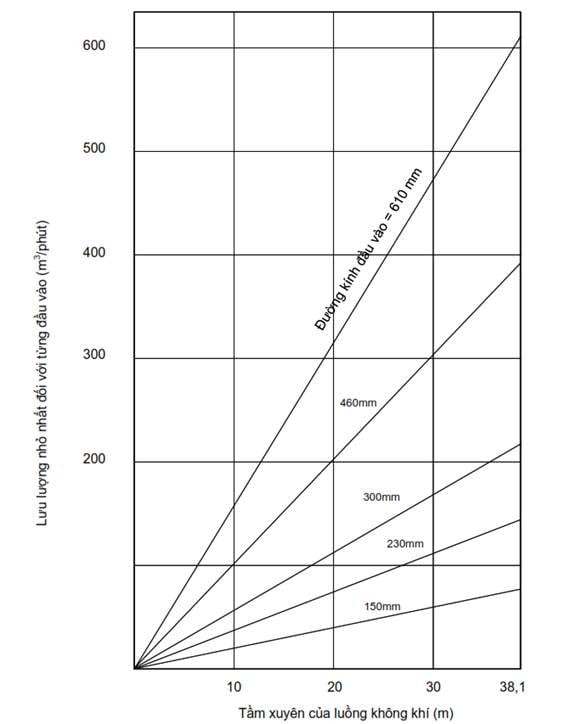
Figure
4.1 Minimum Flow Rate as a Function of Jet Penetration Depth
Jet
penetration depth relative to tank height
(3) Arrangements are to be made in
such a way that an air jet is oriented to the tank sump or the suction point as
far as practicable, and that direct impingement of the air jet onto the tank
structural members can be avoided as far as practicable;
(4) Means are to be provided so
that the residues can be removed from the relevant pipelines drained.
(5) The ventilation equipment is to
be sufficiently corrosion resistant for the noxious liquid substances or inert
gas.
3.6.3 Verification device
The verification device is to be
capable of confirming if visible residues are remaining in the tank and the
effect of the ventilated washing either by a visual inspection or equivalent
other means.
3.6.4 Application of National
Technical Regulation on classification and construction of sea-going steel
ships
...
...
...
Hãy đăng nhập hoặc đăng ký Thành viên
Pro tại đây để xem toàn bộ văn bản tiếng Anh.
3.7 Segregated ballast tank
3.7.1 General provisions
1 The capacity of a segregated ballast tank is to be
such that the draughts and trim of the ship meet the following requirements (1)
to (3) where only the segregated ballast tank under consideration is filled
with ballast water:
(1) The moulded draught of the ship
at midship is the value determined by the following formula or more:
1,550 + 0,023 Lf (m)
(2) The aft trim is to be the value
determined by the following formula or less:
1,600 + 0,013 Lf (m)
(3) The propeller is to be totally
immersed in water.
PART 5
SHIPBOARD OIL POLLUTION EMERGENCY PLAN
...
...
...
Hãy đăng nhập hoặc đăng ký Thành viên
Pro tại đây để xem toàn bộ văn bản tiếng Anh.
1.1 General provisions
1.1.1 Application requirement
The requirements in this Part apply
to Shipboard oil pollution emergency plans to be placed on board ships and
offshore drilling rigs and other platforms used for the exploitation of sea-bed
mineral resources.
1.1.2 Equipment requirements
Every oil tanker of 150 gross
tonnage and above, every ship other than an oil tanker of 400 gross tonnage and
above and offshore drilling rigs and other platforms used for the exploitation
of sea-bed mineral resources is to carry on board permanently a Shipboard oil
pollution emergency plan approved by the Society in a place where it is ready
for immediate use. However, unmanned non-self-propelled (UNSP) barges (as
defined in Part 3, 1.1.2-1(9)) need not comply with this requirement.
CHAPTER
2 TECHNICAL REQUIREMENTS
2.1 General provisions
2.1.1 Precautions for preparation
Shipboard oil pollution emergency
plans are to be prepared considering back ground information on the ship
including type and size of the ship, cargo and trade routes so that they are
realistic, practical, and easy to use.
...
...
...
Hãy đăng nhập hoặc đăng ký Thành viên
Pro tại đây để xem toàn bộ văn bản tiếng Anh.
Shipboard oil pollution emergency
plans are to be written in the working language of the master and officers of
the ship. If the language used in the plan is not English, an English
translation is to accompany it for ships not engaged in international voyages.
2. 2 Entries under shipboard oil
pollution emergency plan
2.2.1 Procedures to be followed when
reporting an oil pollution incident
1 It is to be included in the plan that the master or
other person having charge of the ship should inform without delay, of actual
or probable discharge to the nearest coastal States.
2 The following items (1) through (7) are to be entered
as the items to be reported:
(1) Ship name, call sign, flag,
size and type of the ship;
(2) Date and time of incident,
position, course, speed;
(3) Radio station name, date and
time of next report, type and quantity cargo/bunkers on board, shipper;
(4) Brief details of
defects/deficiencies/damage;
...
...
...
Hãy đăng nhập hoặc đăng ký Thành viên
Pro tại đây để xem toàn bộ văn bản tiếng Anh.
(6) Contact details of ship’s
owner/operator/agent including postal address, telephone No. and facsimile No.;
(7) Post-spill actions taken and
ship’s movements.
2.2.2 List of authorities or persons
to be contacted in the event of an oil pollution incident
Coastal State contacts, port
contacts and ship interest contacts, e.g. owners/operators, charterers,
shippers, underwriters, who are to be contacted if the ship is involved in an
oil pollution incident are to be listed and be included in the Appendices.
2.2.3 Actions to be taken
immediately by persons on board the ship to reduce or control the discharge of
oil following the incident
1 At least the following items (1) to (3) are to be
entered for responding to operational spills:
(1) A detailed description of the
action to reduce or control the discharge of oil and persons in charge;
(2) Procedures for removal of oil
spilled and for the proper disposal of removed oil and clean-up materials;
(3) Oil transfer procedures from
the ship to another ship.
...
...
...
Hãy đăng nhập hoặc đăng ký Thành viên
Pro tại đây để xem toàn bộ văn bản tiếng Anh.
(1) Top priority is to be given to
ensuring the safety of the personnel and the ship.
(2) Detailed information on the
damage sustained by the ship and the oil spill incident is to be collected and
evaluated so that actions can be taken to prevent an escalation of the
incident;
(3) Detailed guidance for stability
and stress considerations or a list of information needed for assessments at
the owner’s head office or other entity.
2.2.4 The procedures and point of
contact on the ship for coordinating shipboard activities with the national and
local authorities in combating the pollution
1 It is to be included in the plan that the master and
other person having charge of ships should contact the coastal State for
authorization before actions are taken to mitigate a discharge.
2 Sufficient guidance for the master of the ship on oil
pollution control operations to be developed under the initiative of the owner
is to be included.
3 Information on response systems and organizations of
the coastal States along the trade route of the ship is to be included in the
Appendices.
2.2.5 Other information
VR may request, in addition to the
items specified in 2.2.1 through 2.2.4, other information that would be useful
to the master of the ship when responding to an emergency situation.
...
...
...
Hãy đăng nhập hoặc đăng ký Thành viên
Pro tại đây để xem toàn bộ văn bản tiếng Anh.
In addition to the list specified in
2.2.2 and information shown in 2.2.4-3, the plans and data specified in the
following (1) to (3) are to be appended to the Shipboard oil pollution
emergency plan:
(1) Plans including general
arrangement, midship section, piping diagrams such as cargo oil lines
considered to be used in dealing with an oil spill incident;
(2) Summary flowchart to guide the
master through the various actions and decisions required during an incident
response;
(3) Other items deemed necessary by
the Society.
2.4 Additional requirements for oil
tankers of 5.000 tonnes deadweight and above
2.4.1 Shore-based support
All tankers of 5,000 tonnes
deadweight or more are to have prompt access to computerised, shore-based
damage stability and residual structural strength calculation programs.
PART 6
SHIPBOARD MARINE POLLUTION EMERGENCY PLAN FOR NOXIOUS LIQUID SUBSTANCES
CHAPTER
1 GENERAL PROVISIONS
...
...
...
Hãy đăng nhập hoặc đăng ký Thành viên
Pro tại đây để xem toàn bộ văn bản tiếng Anh.
1.1.1 Application requirement
The requirements in this Part apply
to a Shipboard marine pollution emergency plan for noxious liquid substances to
be placed on board ships.
1.1.2 Equipment requirements
Every ship of 150 gross tonnage and
above certified to carry noxious liquid substances in bulk is to carry on board
permanently a Shipboard marine pollution emergency plan for noxious liquid
substances approved by VR in a place where it is ready for immediate use.
CHAPTER
2 TECHNICAL REQUIREMENTS
2.1 General provisions
2.1.1 Precautions for preparation
A Shipboard marine pollution
emergency plan for noxious liquid substances is to be prepared considering the
many variables including type and size of the ship, cargo and trade routes at
the preparation, and so that it is realistic, practical, and easy to use.
2.1.2 Language
...
...
...
Hãy đăng nhập hoặc đăng ký Thành viên
Pro tại đây để xem toàn bộ văn bản tiếng Anh.
2.1.3 Shipboard marine pollution
emergency plan
In the case of ships to which the
requirements specified in Part 5 hereof also apply, such a plan may be combined
with the Shipboard oil pollution emergency plan required under Part 5. In this
case, the title of such a plan is to be “Shipboard marine pollution emergency
plan”.
2.2 Entries in Shipboard marine
pollution emergency plan for noxious liquid substances
2.2.1 Procedures to be followed when
reporting a noxious liquid substance pollution incident
1 It is to be included in the plan that the master or
other person having charge of the ship should inform without delay, of actual
or probable discharge to the nearest coastal States.
2 The following items (1) through (7) are to be entered
as the items to be reported:
(1) Ship name, call sign, flag,
size and type of the ship;
(2) Date and time of incident,
position, course, speed;
(3) Date and time of next report,
type and quantity of cargo/bunkers on board, shipper;
...
...
...
Hãy đăng nhập hoặc đăng ký Thành viên
Pro tại đây để xem toàn bộ văn bản tiếng Anh.
(5) Brief details of pollution
including type of oil, estimate of quantity lost, cause of spill, possibility
of continued spill, sea and weather conditions;
(6) Contact details of ship’s
owner/operator/agent including postal address, telephone No. and facsimile No.;
(7) Post-spill actions taken and
ship’s movements.
2.2.2 List of authorities or persons
to be contacted in the event of a noxious liquid substance pollution incident
Coastal State contacts, port
contacts and ship interest contacts, who are to be contacted if the ship is
involved in a noxious liquid substance pollution incident, e.g.
owners/operators, charterers, shippers, underwriters, are to be listed and be
included in the Appendices.
2.2.3 Actions to be taken
immediately by persons on board the ship to reduce or control the discharge of
noxious liquid substance following the incident
1 At least the following items (1) to (3) are to be
entered for responding to operational spills:
(1) A detailed description of the
action to reduce or control the discharge of noxious liquid substance, and
persons in charge;
(2) Procedures for removal of the
spilled noxious liquid substance and for proper disposal of the removed noxious
liquid substance and clean-up materials;
...
...
...
Hãy đăng nhập hoặc đăng ký Thành viên
Pro tại đây để xem toàn bộ văn bản tiếng Anh.
2 At least the following items (1) to (3) are to be
entered to respond to spills resulting from casualties:
(1) Top priority is to be given to
ensuring the safety of the personnel and the ship;
(2) Detailed information on the
damage sustained by the ship and on the noxious liquid substance spill incident
is to be collected and evaluated so that actions can be taken to prevent
escalation of the incident;
(3) Detailed guidance to consider
stability and strength and a list of information needed for damage stability
and strength assessments at the owner’s head office or other similar places.
2.2.4 The procedures and point of
contact on the ship for coordinating shipboard activities with the national and
local authorities in combating the pollution
1 It is to be included in the plan that the master and
other person having charge of ships should contact the coastal State for
authorization before actions are taken to mitigate a discharge.
2 Sufficient guidance for the master of the ship on oil
pollution control operations to be developed under the initiative of the owner
is to be included.
3 Information on response systems and organizations of
the coastal States along the trade route of the ship is to be included in the
Appendices.
2.2.5 Other information
...
...
...
Hãy đăng nhập hoặc đăng ký Thành viên
Pro tại đây để xem toàn bộ văn bản tiếng Anh.
2.3 Appendices of Shipboard marine
pollution emergency plan for noxious liquid substances
In addition to the list specified in
2.2.2 and information shown in 2.2.4-3, the plans and items specified in the
following (1) to (3) are to be appended to a Shipboard marine pollution
emergency plan for noxious liquid substances:
(1) Plans including general
arrangement, midship section, piping diagrams such as cargo oil lines
considered to be used in dealing with an oil spill incident;
(2) Summary flowchart to guide the
master through the various actions and decisions required during an incident
response;
(3) Other items deemed necessary by
the Society.
PART 7
EQUIPMENT FOR PREVENTION OF POLLUTION BY SEWAGE
CHAPTER
1 GENERAL PROVISIONS
1.1 General provisions
1.1.1 Application requirement
...
...
...
Hãy đăng nhập hoặc đăng ký Thành viên
Pro tại đây để xem toàn bộ văn bản tiếng Anh.
2 For unmanned non-self-propelled (UNSP) barges, the
following 2.2 need not be applied when exemptions are granted by VR.
1.1.2 Definitions
1 In this Part, the definitions below have their
meaning attributed to them as follows:
(1) “New ship” means a ship:
(a) For which the building contract
is placed, or, in the absence of a building contract, is at beginning of
construction on or after September 27, 2003; or
(b) The delivery of which is on or
after 27 September 2006.
(2) “Existing ship” means a ship
which is not a new ship.
(3) “Sewage” means:
(a) Drainage and other wastes from
any form of toilets and urinals;
...
...
...
Hãy đăng nhập hoặc đăng ký Thành viên
Pro tại đây để xem toàn bộ văn bản tiếng Anh.
(c) Drainage from spaces containing
living animals;
(d) Other waste waters when mixed
with the drainage defined above.
(4) “Holding tank” means a tank
used for the collection and storage of sewage.
(5) “Special area” means the
following areas:
(a) The Baltic Sea area
The Baltic Sea proper with the Gulf
of Bothnia, the Gulf of Finland and the entrance to the Baltic Sea bounded by
the parallel of the Skaw in the Skagerrak at 57°44.8 N.
(b) Any other sea area than (a)
above, designated by the IMO in accordance with criteria and procedures for
designation of special areas with respect to prevention of pollution by sewage
from ships.
(6) “Person” means member of the
crew and passengers.
(7) “Passenger ship” means a ship
which carries more than 12 passengers. Where a passenger is every person other
than the following (a) and (b):
...
...
...
Hãy đăng nhập hoặc đăng ký Thành viên
Pro tại đây để xem toàn bộ văn bản tiếng Anh.
(b) a child under one year of age.
(8) “New passenger ship” is a
passenger ship:
(a) For which the building contract
is placed, or in the absence of a building contract, the keel of which is laid,
or which is in similar stage of construction, on or after June 1, 2019. For
this purpose, the wording “a similar stage of construction” means the stage
which falls under (a) and (b) of 1.2.2-1(25) Section I; or
(b) The delivery of which is on or
after June 1, 2021.
(9) “Existing passenger ship” is a
passenger ship which is not a new passenger ship.
(10) “Unmanned non-self-propelled
barge” (UNSP) is a barge which:
(a) is not outfitted with means of
mechanical propulsion;
(b) is not occupied by people and livestock;
(b) is not used to contain
wastewater in transport;
...
...
...
Hãy đăng nhập hoặc đăng ký Thành viên
Pro tại đây để xem toàn bộ văn bản tiếng Anh.
CHAPTER
2 EQUIPMENT FOR PREVENTING POLLUTION CAUSED BY SHIPBOARD SEWAGE
2.1 General provisions
2.1.1 Application requirement
1 The requirements of this Chapter apply to the
following ships engaged in international voyages:
(1) New ships of 400 tonnage and
above;
(2) New ships of less than 400
gross tonnage which are certified to carry more than 15 persons; and
(3) Existing ships of 400 gross
tonnage and above, on 27 September 2008; and
(4) Existing ships of less than 400
gross tonnage which are certified to carry more than 15 persons, on 27 September
2008.
2 Existing ships, according to -1(3) and (4) above, the
keel of which are laid or which are of a similar stage of construction before 2
October 1983 are to be equipped, as far as practicable, to discharge sewage in
accordance with the requirements of 2.2.1.
...
...
...
Hãy đăng nhập hoặc đăng ký Thành viên
Pro tại đây để xem toàn bộ văn bản tiếng Anh.
2.2.1 Equipment for the prevention
of pollution by sewage
1 For ships specified in 2.1.1-1, the following
equipment for the prevention of pollution by sewage is to be installed:
(1) One of following sewage systems
(a) A sewage treatment plant in
compliance with -2 below;
(b) A sewage comminuting and
disinfecting system in compliance with -3 below, accompanied with facilities
for the temporary storage of sewage when the ship is less than 3 nautical miles
from nearest land; or
(c) A holding tank of the capacity
for the retention of all sewage, having regard to the operation of the ship,
the number of person on board and other relevant factors. The holding tank is
to be constructed to the satisfaction of VR and to have a means to indicate
visually the amount of its contents. The capacity of the tank is to comply with
the following formula:
CT ≥ ANpDa+R
Where:
CT: Capacity of the
holding tank (m3);
...
...
...
Hãy đăng nhập hoặc đăng ký Thành viên
Pro tại đây để xem toàn bộ văn bản tiếng Anh.
Np: The total number of
persons on board;
Da: the maximum number of
days operating in areas where the discharge of sewage which is not comminuted
or disinfected into the sea is prohibited (minimum 1 day);
R: Initial flush water capacity
necessary according to washing method, etc.
(2) A pipeline to discharge sewage
to a reception facility;
(3) A standard discharge connection
fitted for the pipeline specified in (2) in accordance with Schedule 7.1. For
ships in dedicated trades, alternatively the ship's discharge pipeline may be
fitted with a discharge connection which can be accepted by the Administration,
such as quick-connection couplings.
2 The sewage treatment plant required in -1(1)(a) above
is to be type approved by VR in accordance with MEPC.227(64), except 4.2 of the
Annex to the aforementioned resolution, and to have a sufficient capacity to
treat that calculated by A and Np in -1(1)(c) above as a standard.
3 The sewage comminuting and disinfecting system in
-1(1)(b) above is to be type approved by VR in accordance with MEPC.227(64) and
to have a sufficient capacity to comminute and disinfect that calculated by A
and Np in -1(1)(c) above as a standard.
Schedule
7.1 Standard dimensions of flanges for discharge connection
Description
...
...
...
Hãy đăng nhập hoặc đăng ký Thành viên
Pro tại đây để xem toàn bộ văn bản tiếng Anh.
Outer diameter
210 mm
Inner diameter
Corresponding
to outer diameter (*)
Bolt circle diameter
170 mm
Slots in flange
4 holes of 18 mm in diameter
equidistantly placed on a bolt circle of the above diameter slotted to the
flange periphery. The slot width to be 18 mm
Flange thickness
...
...
...
Hãy đăng nhập hoặc đăng ký Thành viên
Pro tại đây để xem toàn bộ văn bản tiếng Anh.
Bolts and nuts: quantity and
diameter
4, each of 16 mm in diameter and
of suitable length
The flange is designed to accept
pipesup to a maximum internal diameter of 100 mm and is to be of steel or
other equivalent material having a flat face. This flange, together with a
suitable gasket, is to be suitable for a service pressure of 0.6 MPa.
Note:
(*) For ships a molded depth of 5 m and
less, the inner diameter of the discharge connection may be 38 mm.
2.2.2 Regulation on the calculation
of the discharge rate of untreated sewage from ships
1 In case ships specified in 2.1.1-1 are provided with
the holding tank for the retention of untreated sewage from ships in
2.2.1-1(1)(c) above, a calculation sheet of maximum permissible discharge rate
is to be approved by VR for the onboard usage, in accordance with the following
requirements:
(a) The maximum permissible
discharge rate is to be calculated by the following formula:
DRmax = 0,00926VdB
...
...
...
Hãy đăng nhập hoặc đăng ký Thành viên
Pro tại đây để xem toàn bộ văn bản tiếng Anh.
DRmax : Maximum permissible discharge rate (m3/h);
V : Ship’s average speed (knots)
over the period;
d : Draft (m);
B : Breadth (m).
(b) Requirements for the maximum
permissible discharge rate calculation sheet
The maximum permissible discharge
rate calculation sheet is to be presented in tabular format, based on the
formula in (a) above, in accordance with the following requirements (i) to
(iv):
(i) Average speed is to be recorded
in 2 knot increments from 4 knots up to the maximum service speed;
(ii) Draft is to be recorded in 1m
increments from the minimum operating draft up to the maximum summer draft;
(iii) The maximum permissible
discharge rate refers to the average rate as calculated over any 24 hour
period, or the period of discharge if that is less, and may be exceeded by no
more that 20% when measured on an hourly basis;
...
...
...
Hãy đăng nhập hoặc đăng ký Thành viên
Pro tại đây để xem toàn bộ văn bản tiếng Anh.
PART 8
EQUIPMENT FOR PREVENTING SHIPBOARD AIR POLLUTION
CHAPTER
1 GENERAL PROVISIONS
1.1 General provisions
1.1.1 Application requirement
1 The requirements in this Part apply to the equipment
for the prevention of air pollution from sea-going ships and fixed offshore
platforms, mobile offshore units and floating storage units used for the
exploitation of sea-bed mineral resources. However, the requirements of this
Part need only apply to fixed offshore platforms of which building contract is
placed on or after 1 July 2017.
2 Notwithstanding the -1, emissions from mobile
offshore drilling units, etc. directly arising from the exploration,
exploitation and associated offshore processing of sea-bed mineral resources
may be exempted from the provisions of this Part. Such emissions include the
followings:
(1) Emissions resulting from the
incineration of substances that are solely and directly the result of
exploration, exploitation and associated offshore processing of sea-bed mineral
resources, including but not limited to the flaring of hydrocarbons and the
burning of cuttings, muds, and/or stimulation fluids during well completion and
testing operations, and flaring arising from upset conditions;
(2) The release of gases and
volatile compounds entrained in drilling fluids and cuttings;
(3) Emissions associated solely and
directly with the treatment, handling, or storage of sea-bed minerals;
...
...
...
Hãy đăng nhập hoặc đăng ký Thành viên
Pro tại đây để xem toàn bộ văn bản tiếng Anh.
3 In respect of UNSP, requirements under 1.2.1, 2.1,
2.2, and 2.4 shall not be mandatory where VR deems appropriate.
1.1.2 Definitions
1 For the purpose of the requirements in this Part, the
following definitions apply unless specified otherwise in Chapters 2 or 3:
(1) “NOx Technical Code”
means the Technical Code on Control of Emission of Nitrogen Oxides from Marine
Diesel Engines adopted by the International Conference of Parties to MARPOL
73/78 in 1997 as resolution 2, as amended by the IMO, provided that such
amendments are adopted and brought into force in accordance with the provisions
of article 16 of the present Convention;
(2) “Ozone depleting substances”
means controlled substances defined in paragraph 4 of Article 1 of the Montreal
Protocol on Substances that Deplete the Ozone Layer, 1987, listed in Annexes A,
B, C or E to the said Protocol.
(3) “Marine pollutant” means those
substances subject to Annex III;
(4) “Diesel engine manufacturer,
etc.” means the diesel engine manufacturer or other responsible party who
applies for the emission verification, component confirmation, emission
testing, document examination and survey, etc. listed in 2.1.3-5(3) (excluding
(d)(iii)) Part 2’
(5) “Engine Family” means a series
of diesel engines to which the guidance specified in 4.3.8 of the NOx
Technical Code applies. These diesel engines are series produced, proven to
have similar NOx emission characteristics through their design, used
as produced, and, during installation on board, and require no adjustments or
modifications which could adversely affect the NOx emissions;
(6) “Engine Group” means a series
of diesel engines to which the guidance specified in 4.4.6 of the NOx
Technical Code applies. These diesel engines form a smaller series, produced
for similar engine application, and may require minor adjustments and
modifications during installation or in service on board.
...
...
...
Hãy đăng nhập hoặc đăng ký Thành viên
Pro tại đây để xem toàn bộ văn bản tiếng Anh.
(8) “Components of a diesel engine”
mean those interchangeable parts which influence the NOx emissions
performance, identified by their design/parts number;
(9) “Operating values of a diesel
engine” mean engine data, like cylinder peak pressure, exhaust gas temperature,
etc., from the engine log which are related to the NOx emission performance.
These data are load-dependent;
(10) “Technical File” means a
record containing all details of parameters, including components and settings
of a diesel engine, which may influence the NOx emission of the
engine.
(11) “Setting” of a diesel engine
means adjustment of an adjustable feature influencing the NOx
emissions performance of a diesel engine;
(12) “Substantial modification of a
diesel engine” means as follows:
(a) For diesel engines installed on
ships engaged in international voyages having beginning stage of construction
on or after 1 January 2000 (diesel engines installed on ships not engaged in
international voyages having beginning stage of construction on or after 1
January 2021), substantial modification means any modification to an engine
that could potentially cause the NOx emission from the engine to
exceed the limits specified in 2.1.2-1. Routine replacement of components of a
diesel engine by parts specified in the Technical File that do not alter NOx
emission characteristics is not be considered a substantial modification;
(b) For diesel engines installed on
ships engaged in international voyages having beginning stage of construction
before 1 January 2000 (diesel engines installed on ships not engaged in international voyages having
beginning stage of construction before 1 January 2021), substantial
modification means any modification made to an engine which increases its
existing NOx emission characteristics in excess of the limits
established by the on-board simplified measurement method referred to in
2.1.2-2(2)(b). These changes include, but are not limited to, changes in its
operations or in its technical parameters (e.g., changing camshafts, fuel
injection systems, air systems, combustion chamber configuration, or timing
calibration of the engine). However, installation compliant with 2.1-3 or
certified for compliance with 2.1.2-1(1)(a) through (c) shall not be considered
substation modification for the purpose of applying (13) and 2.1.2-1(2).
(13) “Major conversion” of a diesel
engine means a modification of a diesel engine on or after 1 January 2000 (1
January 2021 for ships not engaged in international voyages) which corresponds
to any of the following (a) to (c):
(a) The engine is replaced or
supplemented with a non-identical diesel engine manufactured. Identical diesel
engines means that for both the replacement diesel engine and the diesel engine
being replaced the following items are the same:
...
...
...
Hãy đăng nhập hoặc đăng ký Thành viên
Pro tại đây để xem toàn bộ văn bản tiếng Anh.
(ii) Rated power;
(iii) Rated speed;
(iv) Use;
(v) Number of cylinders;
(vi) Fuel system type (including injection control
software, if applicable);
(vii) For engines not certified to
the standards set forth in 2.1.2-1 of this Part, the NOx critical
components and settings (fuel pump model and injection timing, injection nozzle
model, configuration, turbocharger model and auxiliary blower specification,
cooling medium (seawater/freshwater), etc.); and
(viii) For engines certified to the
standards set forth in 2.1.2-1 of this Part, the engine group or engine family
to which these diesel engines belong.
(b) Any substantial modification of
a diesel engine is made to the engine.
(c) The maximum continuous output
(referred to in 1.2.41 Part 1A Section II of the National Technical Regulation
on classification and construction of sea-going steel ships, hereinafter the
same) of the engine is increased to more than 10%.
...
...
...
Hãy đăng nhập hoặc đăng ký Thành viên
Pro tại đây để xem toàn bộ văn bản tiếng Anh.
(15) “NOx emission
control areas” means the following areas:
(a) The North American area
(i) The sea area located off the
Pacific coasts of the United States and Canada, enclosed by geodesic lines
connecting the coordinates specified in Appendix VII.1 to Annex VI;
(ii) The sea areas located off the
Atlantic coasts of the United States, Canada, and France
(Saint-Pierre-et-Miquelon) and the Gulf of Mexico coast of the United States
enclosed by geodesic lines connecting the coordinates specified in Appendix
VII.2 to Annex VI;
(iii) The sea area located off the
coasts of the Hawaiian Islands of Hawaii, Maui, Oahu, Molokai, Niihau, Kauai,
Lanai, and Kahoolawe, enclosed by geodesic lines connecting the coordinates
specified in Appendix VII.3 to Annex VI.
(b) The United States Caribbean
area
The sea area located off the
Atlantic and Caribbean coasts of the Commonwealth of Puerto Rico and the United
States Virgin Islands, enclosed by geodesic lines connecting the coordinates
specified in Appendix VII.3 to Annex VI.
(c) The Baltic area
The Baltic Sea proper with the Gulf
of Bothnia, the Gulf of Finland and the entrance to the Baltic Sea bounded by
the parallel of the Skaw in the Skagerrak at 57°44.8 N.
...
...
...
Hãy đăng nhập hoặc đăng ký Thành viên
Pro tại đây để xem toàn bộ văn bản tiếng Anh.
The North Sea area consist seas in
the area and boundary between:
(i) the North Sea southwards of
latitude 62°N and eastwards of longitude 4°W.
(ii) the Skagerrak, the southern
limit of which is determined east of the Skaw by latitude 57°44.8΄ N; and
(iii) the English Channel and its
approaches eastwards of longitude 5°W and northwards of latitude
48°30΄N.";
(e) Any other sea area, including
port areas, designated by the IMO in accordance with criteria and procedures
set forth in Appendix III to Annex VI.
(16) “SOx Emission
Control Areas” means areas, including port areas, defined by IMO compliant with
criteria and procedures under Appendix III to Annex VI. Emission control areas
consist of (a) through (d):
(a) The North American area
The area specified in (a) of (15).
(b) The United States Caribbean
area
...
...
...
Hãy đăng nhập hoặc đăng ký Thành viên
Pro tại đây để xem toàn bộ văn bản tiếng Anh.
(c) The Baltic area
The area specified in (c) of (15).
(d) The North Sea area
The area specified in (d) of (15).
(17) “Tanker” means an oil tanker
as defined in Regulation 1 of Annex I or a chemical tanker as defined in
Regulation 1 of Annex II, and includes any of the following (a) to (c).
(a) Oil tanker
A ship constructed to carry liquid
cargoes in bulk in their cargo spaces (excluding those with cargo spaces which
are adapted to exclusively carry cargo other than oil in bulk);
(b) Ship carrying noxious liquid
substance in bulk
A ship carrying noxious liquid
substance in bulk specified in 1.2.2-1(7) Section I;
...
...
...
Hãy đăng nhập hoặc đăng ký Thành viên
Pro tại đây để xem toàn bộ văn bản tiếng Anh.
A combination carrier specified in
1.2.2-1(8) Section I.
(18) “Fuel oil” means any fuel
delivered to and intended for combustion purposes for propulsion or operation
on board a ship, including gas, distillate and residual fuels.
(19) “Calendar year” means the
period from 1 January until 31 December inclusive;
(20) “Company” means the owner of
the ship or any other organization or person such as the manager, or the
bareboat charterer, who has assumed the responsibility for operation of the ship
from the owner of the ship and who on assuming such responsibility has agreed
to take over all the duties and responsibilities imposed by the International
Management Code for the Safe Operation of Ships and for Pollution Prevention,
as amended.
(21) “Marine diesel engine” means
any reciprocating internal combustion engine operating on liquid or dual fuel,
to which regulation 2.1 applies, including booster/compound systems if applied.
(22) “Installations” in relation to
regulation 1.2.1 means the installation of systems, equipment including
portable fire-extinguishing units, insulation, or other material on a ship, but
excludes the repair or recharge of previously installed systems, equipment,
insulation, or other material, or the recharge of portable fire-extinguishing
units.
(23) “Electronic record” means an
equipment or system approved by the VR to electronically record details
pertaining to discharge, conversion, and other activities in accordance with
this Part as opposed to physical record.
(24) “Electronic record for engine
technical performance characteristics” means an equipment or system approved by
the VR to electronically record details required under this Part, as opposed to
physical record.
(25) “Low-flashpoint fuel” means
gaseous or liquid fuel oil defined under 2.2.1-28 Part 8I of the National
Technical Regulation on classification and construction of sea-going steel
ships.
...
...
...
Hãy đăng nhập hoặc đăng ký Thành viên
Pro tại đây để xem toàn bộ văn bản tiếng Anh.
(27) “Unmanned non-self-propelled
barge” (UNSP) is a barge which:
(a) is not outfitted with means of
mechanical propulsion;
(b) is not outfitted with system,
equipment, and machinery that may produce emission detailed under this Part.
(c) is not occupied by people and livestock;
1.1.3 Equivalent clauses
VR may allow any fitting, material,
appliance or apparatus to be fitted in a ship or other procedures, alternative
fuel oils, or compliance methods used as an alternative to that required by
this Regulation if such fitting, material, appliance or apparatus or other
procedures, alternative fuel oils, or compliance methods are at least as
effective in terms of emissions reductions as that required by this Regulation.
1.2 General clauses
1.2.1 Ozone-depleting substances
1 Requirements under 1.2.1 apply to all equipment,
other than permanently sealed equipment in a manner compliant with requirements
(1) and (2):
...
...
...
Hãy đăng nhập hoặc đăng ký Thành viên
Pro tại đây để xem toàn bộ văn bản tiếng Anh.
(2) Of which detachable elements do
not contain ozone-depleting substances.
2 Equipment containing ozone-depleting substances shall
be so arranged to prevent emission of such ozone-depleting substances if
necessary during maintenance, repair, service, or discard of such system or
equipment.
3 Equipment containing ozone--depleting substances
other than HCFCs must not be installed on:
(1) Ships built on or after May 19,
2005; or
(2) Ships built before May 19, 2005
where:
(a) The equipment is delivered
under contract on or after May 19, 2005; or
(b) In the absence of contractual delivery
date, the equipment is loaded onto ship on or after May 19, 2005.
4 Equipment containing HCFCs shall not be installed on:
(1) Ships built on or after January
01, 2020; or
...
...
...
Hãy đăng nhập hoặc đăng ký Thành viên
Pro tại đây để xem toàn bộ văn bản tiếng Anh.
(a) The equipment is delivered
under contract on or after January 01, 2020; or
(b) In the absence of contractual
delivery date, the equipment is loaded onto ship on or after January 01, 2020.
5 All ships to which International Air Pollution
Prevention (IAPP) Certificate is issued in compliance with 6.1 of Appendix VI
shall keep registers of equipment containing ozone-depleting substances.
6 Each ship which has rechargeable systems that contain
ozone depleting substances is required to maintain an Ozone Depleting
Substances Record Book; the details of which shall be recorded in form of
substance quantity and completed immediately under cases (1) through (5) below:
Such record may constitute
a part of existing ship log or electronic ship log deemed compliant with
MEPC.312(74) by the VR.
(1) Recharge, full or partial, of
equipment containing ozone-depleting substances;
(2) Repair or maintenance of
equipment containing ozone-depleting substances;
(3) Discharge of ozone-depleting
substances to the atmosphere;
(a) Deliberate (including emission
of ozone-depleting substances during maintenance, repair, or discard), and
(b) Non-deliberate.
...
...
...
Hãy đăng nhập hoặc đăng ký Thành viên
Pro tại đây để xem toàn bộ văn bản tiếng Anh.
(5) Supply of ozone-depleting
substances to the ship.
1.2.2 Use and carriage of fuel oil
1 Sulfur content of fuel oil used or transported for
use on ship, including use for emergency equipment shall not exceed 0,5% m/m.
2 Sulfur content of fuel oil where ship operates in an
emission control area shall, in addition to meeting requirements in -1, not
exceed 0,1% m/m.
3 The sulfur content of fuel oil referred to in -1 and
-2 above is to be documented by its supplier as required by Regulation 18 of
Annex VI.
4 Where exhaust gas cleaning system is used to meet
requirements of -1 or -2 as an alternative to the use of fuel oil of which sulfur
content does not exceed 0,5% or 0,01% m/m, such exhaust gas cleaning system
shall conform to MEPC.259(68).
1.2.3 Delivery of fuel oil and
bunker delivery notes
1 Unless otherwise accepted in accordance with 18.2.1
through 18.2.5 of Appendix VI, fuel oil for combustion purposes delivered to and used on board ships is
to meet the following (1) and (2) requirements:
(1) Except as provided in (2)
below, the following (a) to (c) requirements are to be satisfied:
...
...
...
Hãy đăng nhập hoặc đăng ký Thành viên
Pro tại đây để xem toàn bộ văn bản tiếng Anh.
(b) The fuel oil is to be free from
inorganic acid;
(c) The fuel oil is not to include
any added substance or chemical waste which:
(i) jeopardizes the safety of ships
or adversely affects the performance of the machinery;
(ii) is harmful to personnel; or
(iii) contributes overall to
additional air pollution.
(2) The fuel oil derived by methods
other than petroleum refining is not:
(a) to exceed the applicable sulfur
content specified in -1 or -2 of 1.2.2;
(b) to cause the NOx emission from
a diesel engine to exceed the limits specified in 2.1.2-1;
(c) to contain inorganic acid;
...
...
...
Hãy đăng nhập hoặc đăng ký Thành viên
Pro tại đây để xem toàn bộ văn bản tiếng Anh.
(e) to be harmful to personnel;
(f) to contribute overall to
additional air pollution.
2 For each ship of 400 tons gross tonnage or above
engaged in international voyages, details of fuel oil for combustion purposes
delivered to and used on board is to be recorded by means of a bunker delivery
note. The bunker
delivery note is to be retained on board the ship for a period of 3 years after
the fuel oil has been delivered on board. The bunker delivery note is to be
kept on board the ship in such a place as to be readily available for
inspection at all reasonable times.
3 The bunker delivery note referred to -2 is to contain
at least the information specified in Appendix V to Annex VI.
4 The bunker delivery note referred to in -3 is to be
accompanied by a representative sample of the fuel oil delivered obtained in a
way deemed compliant with MEPC.182(59). The sample is to be sealed and signed
by the supplier’s representative and the master or officer in charge of the
bunker operation on completion of bunkering operations and retained on board
the ship in a way deemed compliant with the MEPC.182(59), labeled, named in
English, French, or Spanish until the fuel oil is substantially consumed, but
in any case for a period of not less than 12 months from the time of delivery.
5 The requirements specified in -1 to -4 above do not
apply to coal in its solid form or nuclear fuels. The requirements specified in -2 to
-4 above do not apply to gas fuels such as liquefied natural gas, compressed
natural gas or liquefied petroleum gas. Sulfur content of gas fuels delivered
to a ship specifically for combustion purposes on board that ship is to be
documented by the supplier.
1.2.4 Substances prohibited to be
incinerated on board
1 Substances prohibited to be incinerated on board
ships are those listed below:
(1) Residue of the cargoes listed
in the following (a) through (c) and related contaminated packing materials:
...
...
...
Hãy đăng nhập hoặc đăng ký Thành viên
Pro tại đây để xem toàn bộ văn bản tiếng Anh.
(b) Noxious liquid substance
(c) Marine pollutants.
(2) Polychlorinated biphenyls (PCBS);
(3) Garbage containing heavy
metals;
(4) Refined petroleum products containing
halogen compounds;
(5) Polyvinyl chlorides (PVCs)
(except when incinerated in an incinerator complying with the requirements in
2.4-1(2) or the equivalent);
(6) Sewage sludge and sludge oil
which are not generated by the ship;
(7) Exhaust gas cleaning system
residues.
CHAPTER
2 EQUIPMENT FOR PREVENTING SHIPBOARD AIR POLLUTION
...
...
...
Hãy đăng nhập hoặc đăng ký Thành viên
Pro tại đây để xem toàn bộ văn bản tiếng Anh.
2.1.1 General provisions
1 Regulations in 2.1 apply to each diesel engine
running on liquid fuel or dual fuel and each engine runs on gas fuel on board,
with a power output exceeding 130 kW in any case from (1) through (4):
(1) Engine, notwithstanding engines
running on gas fuel, installed on board of ships built on or after January 1,
2000;
(2) Engine, notwithstanding engines
running on gas fuel, undergoing major conversion on or after January 1, 2000;
(3) Engine, notwithstanding engine
running on gas fuel, installed on board of ships built on or after March 1,
2016; or
(4) Engine running on gas fuel,
additionally installed or replaced to an extent that it is no longer identical
to previous engine, and installed on board on or after March 1, 2016.
2 Notwithstanding regulation of -1, this requirement
does not apply to diesel engines mentioned below:
(1) Engines to be used for
emergency purposes, engines installed on lifeboats and in any equipment used
only in case of emergency;
(2) Engines installed on ships that
are not engaged in international voyages.
...
...
...
Hãy đăng nhập hoặc đăng ký Thành viên
Pro tại đây để xem toàn bộ văn bản tiếng Anh.
4 In respect of marine diesel engines to which EIAPP is
issued for the first time on or after June 1, 2019 and outfitted with exhaust
gas recirculation, such discharge system is to satisfy requirements of
MEPC.307(73) standard approved by the VR.
5 Where marine diesel engines are issued with EIAPP for
the first time on or after June 1, 2019 and outfitted with bleed-off exhaust
gas recirculation, such system must satisfy requirements of MEPC.307(73) or
equivalents.
2.1. 2 Installation requirements
1 In respect of marine diesel engines, exhaust cleaning
system for reducing NOx emission specified under appraised technical
documents is to be installed or other equivalent measures for reducing NOx
approved by the VR are to be adopted in order to ensure that NOx emission
measured and calculated in accordance with -2 below is between permissible
limits under Schedule 8.1(a) through (c) corresponding to the highest engine
revolution (see 1.2.42 Part 1A Section II of the National Technical Regulation
on classification and construction of sea-going steel ships, hereinafter the
same).
(1) Marine diesel engines installed
on ships built on or after January 1, 2000.
(a) Tier I
In respect of ships built on or
after January 1, 2000 but prior to January 1, 2011 outfitted with marine diesel
engines.
Schedule
8.1(a) Maximum permissible NOx emission (tier 1)
Engine
speed N0 (revolution/minute)
...
...
...
Hãy đăng nhập hoặc đăng ký Thành viên
Pro tại đây để xem toàn bộ văn bản tiếng Anh.
N0 < 130
17,0
130 ≤ N0 < 2.000
45,0 ×
N0(-0,2)
2.000 ≤
N0
9.8
(b) Tier II
In respect of ships built on or
after January 1, 2011 and outfitted with marine diesel engines.
Schedule
8.1(b) Maximum permissible NOx emission (tier 2)
...
...
...
Hãy đăng nhập hoặc đăng ký Thành viên
Pro tại đây để xem toàn bộ văn bản tiếng Anh.
Maximum
permissible NOx emission (g/kWh)
N0 < 130
14,4
130 ≤ N0
< 2.000
44,0 ×
N0(-0,23)
2.000 ≤
N0
7,7
(c) Tier III
In respect of the following ships
operating in NOx emission control area and outfitted with marine
diesel engine:
...
...
...
Hãy đăng nhập hoặc đăng ký Thành viên
Pro tại đây để xem toàn bộ văn bản tiếng Anh.
(ii) Ships operating in other
emission control areas other than those specified in 1.1.2(15)(a) and (b) and
built on or after the date on which IMO approves such NOx emission
control zones or the date after that prescribed by IMO in accordance with
13.5.1.2 of Annex VI, whichever is later.
Schedule
8.1(c) Maximum permissible NOx emission (tier III)
Engine
speed N0 (revolution/minute)
Maximum
permissible NOx emission (g/kWh)
N0 < 130
3,4
130 ≤ N0 < 2.000
9,0 × N0(-0,2)
2.000 ≤
N0
...
...
...
Hãy đăng nhập hoặc đăng ký Thành viên
Pro tại đây để xem toàn bộ văn bản tiếng Anh.
(d) Requirements under (c) do not
apply to:
(i) Ships under 24 m in length,
specifically designed and used for recreational purposes; or
(ii) Ships of total power capacity
of marine diesel engine under 750 kW adequately proven to VR to be incapable of
satisfying standards under Schedule 8.1(c) due to ship design or structure
limitations; or
(iii) Ships of a gross tonnage
below 500, at least 24 m in length, and built on or after January 1, 2021,
specifically designed and used for recreational purposes.
(2) Major conversion of marine
diesel engines implemented on or after January 1, 2000
Where a marine diesel engine is
replaced by an engine that is not identical to the previous engine or is
additionally installed, standards applicable on the date on which such
replacement or additional installation takes place are to be adopted. However,
in respect of engine replacement, where the VR deems engine replacement
satisfactory to standards under Schedule 8.1(c), such replacement engine is to
satisfy requirements under Schedule 8.1(b). Criteria for determining when
engine replacement satisfactory to Schedule 8.1(c) is not feasible shall
conform to guidelines of IMO under MEPC.230(65).
2 Measurement and calculation shall satisfy
requirements below:
(1) NOx emission is to
be measured and calculated in order to adopt inspection cycle compliant with
(a) through (d) below. Data collected via other tests are not to be used to
calculate emission values:
(a) For constant-speed marine
engines, including engines used as main propulsion of diesel-electric drive,
test cycle E2 under Schedule 8.2 shall be applied;
...
...
...
Hãy đăng nhập hoặc đăng ký Thành viên
Pro tại đây để xem toàn bộ văn bản tiếng Anh.
(c) For constant-speed auxiliary
engines test cycle D2 under Schedule 8.4 shall be applied;
(d) For variable-speed,
variable-load auxiliary engines, not included in (a) through (c) above, test
cycle C1 under Schedule 8.5 shall be applied.
(2) NOx emission shall be inspected
via any of measurement method below and conform to cycle under -5:
(a) Measurement procedure for
inspecting NOx emission at test bed;
(b) Simplified on-board
measurement;
(c) Direct measurement and
supervision on board.
(3) Measurement shall utilize DM or
RM grade fuels (RM grade fuel is only used for measurement procedures for
inspecting emission on test bed if DM grade fuel is not available) according to
IS 8217:2005 or gas fuel compliant with NOx Technical Code and
suitable with engine characteristics. However, where suitable fuel oils are not
available, other fuel oils approved by the VR can be used;
(4) NOx emission value and limit
shall be rounded to 1 decimal place.
3 Where an additional auxiliary substance is added,
such as ammonia, urea, steam, water, fuel oil additives, etc., means for controlling
consumption rate of such substance are to be adopted.
...
...
...
Hãy đăng nhập hoặc đăng ký Thành viên
Pro tại đây để xem toàn bộ văn bản tiếng Anh.
5 NOx measurement procedures
(1) Measurement procedures on test
bed
The procedures are to be compliant
with Chapter 5 of the NOx Technical Code. In addition, procedures
related to marine diesel engines outfitted with abatement equipment “selective
catalytic reduction” are to be compliant with MEPC.291(71) and amendments,
supplements thereto;
(2) Simplified on-board measurement
This measurement procedure is to be
compliant with 6.3 of the NOx Technical Code. However, for the
purpose of evaluation in accordance with request under 2.1.3-5(3)(a)(iv)2) Part
2 compliant with simplified on-board measurement, permissible deviations under
6.3.11 of the NOx Technical Code will not apply. In addition,
procedures detailed under Chapter 5 of the NOx Technical Code if adopted shall
conform to (1) above;
(3) Direct on-board measurement and
monitoring method
This measurement method is to be
compliant with 6.4 and Appendix VIII of the NOx Technical Code. In
addition, provisions under (a) through (g) below must be satisfied:
(a) Data is collected in the last
30 days compliant with (i) or (ii):
(i) Results of irregular inspection
are recorded together with operational data of marine diesel engines on the
basis of regular operation and in all operating range of engines; or
...
...
...
Hãy đăng nhập hoặc đăng ký Thành viên
Pro tại đây để xem toàn bộ văn bản tiếng Anh.
(b) Supervision records are to be
kept on-board for 3 months;
(c) Data are to be calibrated on
the basis of environmental and fuel oil characteristics;
(d) Measuring instruments are to be
inspected by manufacturing facilities, operational, and calibrated in
accordance with procedures provided under technical documents of engine;
(e) Where installation of exhaust
treatment equipment affects NOx emission, measurement points are to
be situated along exhaust stream after such equipment;
(f) Adequate data are to be
collected to calculate practical mean NOx emission;
(g) Where exhaust cleaning system
is installed for marine diesel engines to abate NOx emission,
appropriate observable parameters are to be approved by the VR.
Schedule
8.2 E2 test cycle
Speed
100%
...
...
...
Hãy đăng nhập hoặc đăng ký Thành viên
Pro tại đây để xem toàn bộ văn bản tiếng Anh.
100%
100%(2)
Power
100%
75%
50%
25%
Weighting
factor(1)
0,2
...
...
...
Hãy đăng nhập hoặc đăng ký Thành viên
Pro tại đây để xem toàn bộ văn bản tiếng Anh.
0,15
0,15
Schedule
8.3 E3 test cycle
Speed
100%
91%
80%
63%
Power
...
...
...
Hãy đăng nhập hoặc đăng ký Thành viên
Pro tại đây để xem toàn bộ văn bản tiếng Anh.
75%
50%
25%
Weighting
factor(1)
0,2
0,5
0,15
0,15
Schedule
8.4 D2 test cycle
...
...
...
Hãy đăng nhập hoặc đăng ký Thành viên
Pro tại đây để xem toàn bộ văn bản tiếng Anh.
100%
100%
100%
100%
Power
100%
75%
25%
10%
...
...
...
Hãy đăng nhập hoặc đăng ký Thành viên
Pro tại đây để xem toàn bộ văn bản tiếng Anh.
0,05
0,25
0,3
0,1
Schedule
8.5 C1 test cycle
Speed
Rated
Intermediate(4)
Idle
...
...
...
Hãy đăng nhập hoặc đăng ký Thành viên
Pro tại đây để xem toàn bộ văn bản tiếng Anh.
100%
75%
50%
10%
100%
75%
50%
0%
Weighting
factor(1)
...
...
...
Hãy đăng nhập hoặc đăng ký Thành viên
Pro tại đây để xem toàn bộ văn bản tiếng Anh.
0,15
0,15
0,1
0,1
0,1
0,1
0,15
Note:
(1) Value is specified under 5.12.6 of
the NOx Technical Code;
...
...
...
Hãy đăng nhập hoặc đăng ký Thành viên
Pro tại đây để xem toàn bộ văn bản tiếng Anh.
(3) Ratio between the required torque
and highest torque at determined speed;
(4) Provided by engine manufacturer,
taking into account:
(a) For engines that are designed
to operate over a speed range on a full load torque curve:
(i) If the declared maximum torque
speed is less than 60% of rated speed, then the intermediate speed shall be 60%
of the rated speed;
(ii) The intermediate speed shall
be the declared maximum torque speed if it occurs between 60% and 75% of rated
speed;
(i) If the declared maximum torque
speed is greater than 75% of the rated speed, then the intermediate speed shall
be 75% of rated speed.
(b) For engines that are not
designed to operate over a speed range on the full load torque curve at steady
state conditions, the intermediate speed will typically be between 60% and 75%
of the maximum rated speed.
2.1.3 Technical files and engine
specification record books
1 Technical files
...
...
...
Hãy đăng nhập hoặc đăng ký Thành viên
Pro tại đây để xem toàn bộ văn bản tiếng Anh.
(1) Identification of those
components, settings and operating values of the engine that influences its NOx
emissions including any NOx emission reducing device or system;
(2) Identification of the full
range of allowable adjustments or alternatives for the components of the
engine;
(3) Full record of the relevant
engine's performance, including the engine's rated speed and rated power;
(4) At least any of NOx
emission evaluation methods provided under 2.1.2-2(2) and adoption capability
in inspection under 3.2.2-4(2) Part 2, or inspection method for on-board marine
diesel engine specifications, compliant with 6.2 of the NOx
Technical Code. Where direct on-board measurement and monitoring method is
adopted, procedures for calibrating and employing measuring instruments
provided by marine diesel engine manufacturing are required. In addition, where
exhaust cleaning system is installed to reduce NOx emission,
on-board procedures for determining NOx are to be provided;
(5) A copy of test data compliant
with Part 2 Annex V of the NOx Technical Code (where simplified
on-board measurement is adopted compliant with 2.2.5.2 of the NOx
Technical Code to evaluate emission, both test records are required). In
respect of engines associated to a family or group of engine, test data of
sample engines shall also suffice;
(6) If applicable, the designation
and restrictions for an engine that is an engine within an engine family or
engine group in accordance with requirements under Chapter 4 of the NOx
Technical Code;
(7) Specifications of those spare
parts/components that, when used in the engine, according to those specifications,
will result in continued compliance of the engine with the applicable NOx
compliant with 2.1.2-1;
(8) The EIAPP Certificate, as
applicable;
(9) Where exhaust cleaning system
is installed to reduce NOx emission, written records shall include
presence of such system as a component of marine diesel engine;
...
...
...
Hãy đăng nhập hoặc đăng ký Thành viên
Pro tại đây để xem toàn bộ văn bản tiếng Anh.
(11) Relevant information.
2 Engine specification record books
Each engine is to be accompanied by
an specification record books or electronic specification record books which
contain recordings of all amendments, revision, changes to specifications,
including to components and settings of the engine that may affect NOx emission
after technical documents are appraised.
2.1.4 Recording information related
to NOx emission
The Tier (Tier II or Tier III) and
on/off status of marine diesel engines to which 2.1.2-1(1)(c) applies and which
are certified to both Tier II and Tier III or which are certified to Tier II
only shall be recorded in such logbook or electronic record book, as deemed by
the VR compliant with MEPC.312(74) together with the date, time and position of
the ship in the following cases:
(1) Upon entering a NOx
emission control area under 1.1.2(15);
(2) Upon leaving a NOx
emission control area under 1.1.2(15); or
(3) Upon changing on/off status in
a NOx emission control area under 1.1.2(15).
2.2 Sulfur oxide (SOx)
and particulate matters
...
...
...
Hãy đăng nhập hoặc đăng ký Thành viên
Pro tại đây để xem toàn bộ văn bản tiếng Anh.
1 For ships using different fuel oil types compliant
with 1.2.2-2 and entering or leaving SOx emission control area,
procedures for fuel oil conversion with sufficient time to enable fuel oil
system to remove fuel oil of which sulfur contents exceed the limit under
1.2.2-2 before entering the emission control area. Volume of fuel oil of which sulfur
contents are low (satisfactory to 1.2.2-2) in each tank, information on time,
date, and ship location compliant with cases (1) and (2) below are to be
recorded in logbook or electronic record books deemed by the VR compliant with
MEPC.312(74).
(1) Upon completion of fuel oil
conversion before entering SOx emission control area in order to
completely remove all fuel oil used outside of the area and start using fuel
oil compliant with 1.2.2-2;
(2) Upon starting to convert fuel
oil after leaving SOx emission control area and use regular fuel
oils outside of the area.
2 Within the first 12 months from the date on which a
SOx emission control area is established, requirements under 2.2.1
do not apply to the use of fuel oil in said area.
2.2.2 In-use sampling points
1 Ships (including mobile platforms and other
platforms) of a gross tonnage 400 or higher and engaged in international
voyages, built on or after April 1, 2022 shall be so outfitted with or
designated sampling points where representative samples (in-use samples) of
fuel oil are collected in accordance with MEPC.1/Circ 864/rev.1 - Guidelines
for on board sampling for the verification of the sulfur content of the fuel
oil used on board ships, 2019, amendments thereto.
2 Ships (including mobile platforms and other
platforms) of a gross tonnage above 400 and engaged in international voyages,
built before April 1, 2022 shall be outfitted with or designated sampling
points mentioned in -1 at a date not later than the first periodic inspection
on or after April 1, 2023.
3 Requirements under -1 and -2 do not apply to systems
serving fuel oil in respect of fuel with low flash point used for propulsion or ship operations.
2.3 Vapour collection system
...
...
...
Hãy đăng nhập hoặc đăng ký Thành viên
Pro tại đây để xem toàn bộ văn bản tiếng Anh.
(1) Bulk cargo ships;
(2) Ships carrying liquefied gas in
bulk (where cargo handling and storage system allows safe storage of VOCs that
do not contain methane and safe discharge on shore).
2 For ships outfitted with vapour collection system
under -1, guidelines relating to system operating and containing information
below are to be provided:
(1) Piping diagram;
(2) Maximum permissible transfer
rates;
(3) Maximum pressure drop in the
vessel's vapour collection system for various transfer rates;
(4) Relief setting of each pressure
and vacuum relief valve;
(5) Pre-transfer procedures; and
(6) Other procedures to be followed
not specified in (1) through (5)
...
...
...
Hãy đăng nhập hoặc đăng ký Thành viên
Pro tại đây để xem toàn bộ văn bản tiếng Anh.
(1) Procedures are provided to
minimize VOC emission during loading, voyage, and unloading;
(2) Accounts are to be taken for
VOCs produced by crude oil washing;
(3) Person responsible for
implementation of the Plan is defined;
(4) For ships engaged in
international voyages, such Plan is to be presented in working languages of
masters and officers. Where working languages of masters and officers are not
English, French, or Spanish, a translation to any of these languages is to be
provided.
4 Vapour collection system must satisfies requirements
below:
(1) VR deems compliant with
MSC/Circ.585 of IMO;
(2) Components must include:
(a) Vapour inlet ducts;
(b) Liquid gauge;
...
...
...
Hãy đăng nhập hoặc đăng ký Thành viên
Pro tại đây để xem toàn bộ văn bản tiếng Anh.
(d) Pressure gauge.
2.4 Waste incinerators
1 For each ship on which waste or other substances
produced during normal ship operation are incinerated, incinerating equipment
satisfactory to requirements below is to be provided. However, incineration of wastewater
or sludge oil (collected from filtration of fuel oil or lubricants, lubricants
residue of main propulsion or secondary propulsion, sludge oil from filter or
trays) can be implemented in marine diesel engine or boilers where the ships
are outside of port waters, docks, and estuaries.
(1) Waste incinerators are to be designed
for the primary purpose of incinerating wastes, etc.;
(2) Each waste incinerator
installed onboard on or after January 1, 2000 is to satisfy requirements below:
However, waste incinerators installed onboard before May 19, 2005 can be
exempted from the requirement (2) as long as the ships on which they are
installed are not engaged in international voyages;
(a) Is to be recognized by the VR
for compliance with MEPC.244(66) and, upon using standard oil/waste according
to Schedule 8.6, operating within limits defined under Schedule 8.7;
(b) It is to be capable of
monitoring of combustion flue gas outlet temperature at all times;
(c) In case waste is fed into the
combustion chamber without human assistance while the incinerator is in normal
operating conditions, waste is not to be fed into the unit when the combustion
chamber gas outlet temperature is below 850 oC;
(d) For batch-loaded incinerators,
the unit is to be designed so that the combustion chamber gas outlet
temperature is to reach 600 oC within 5 minutes after start-up and
is to thereafter stabilize at a temperature not less than 850 oC.
...
...
...
Hãy đăng nhập hoặc đăng ký Thành viên
Pro tại đây để xem toàn bộ văn bản tiếng Anh.
Oil/waste
Composition
Sludge oil
Sludge oil from heavy fuel oil
75%
Waste lubricating oil
5%
Emulsified water
20%
...
...
...
Hãy đăng nhập hoặc đăng ký Thành viên
Pro tại đây để xem toàn bộ văn bản tiếng Anh.
(Mixture will have up to 50% moisture and 7%
incombustible solids)
Food waste
50%
Rubbish
50%
Component
Paper
15%
Cardboard
...
...
...
Hãy đăng nhập hoặc đăng ký Thành viên
Pro tại đây để xem toàn bộ văn bản tiếng Anh.
Rags
5%
Plastic
10%
2 All ships outfitted with waste incinerators compliant
with -1(2) shall be so required to carry operation manuals provided by
manufacturers. Such
manuals shall provide instruments on operation waste incinerators within the
limits defined under Schedule 8.7 and include:
(1) Drawings;
(2) Electric diagrams;
(3) Instruction and maintenance
manual.
3 Every incinerator is to be operated by a trained
personnel in accordance with an operating manual.
...
...
...
Hãy đăng nhập hoặc đăng ký Thành viên
Pro tại đây để xem toàn bộ văn bản tiếng Anh.
Item
Limit
O2 in combustion
chamber
6-12%
CO in flue gas maximum average
220
mg/MJ
Soot number maximum average
BACHARACH 3 or RINGELMAN 1 (20%
opacity) (A higher soot number is acceptable only during very short periods
such as starting up)
Unburned components in ash
residues
...
...
...
Hãy đăng nhập hoặc đăng ký Thành viên
Pro tại đây để xem toàn bộ văn bản tiếng Anh.
Combustion chamber flue gas outlet
temperature range
850 ºC - 1200 ºC
CHAPTER
3 ENERGY EFFICIENCY OF SHIPS
3.1 General provisions
3.1.1 Objectives
The goal of this Chapter is to
reduce the carbon intensity of international shipping, working towards the
“levels of ambition” set out in the Initial IMO Strategy on reduction of GHG
emissions from ships”.
3.1.2 Functional requirements
In order to achieve 3.1.1 above,
ships subject to this chapter are to comply, as applicable, with the following
functional requirements (1) and (2) to reduce their carbon intensities:
(1) The technical carbon intensity
requirements specified in 3.2 to 3.5;
...
...
...
Hãy đăng nhập hoặc đăng ký Thành viên
Pro tại đây để xem toàn bộ văn bản tiếng Anh.
3.1.3 Scope
1 The requirements in this Chapter apply to all ships
of 400 gross tonnage and above other than those solely engaged in international
voyages. However, they
do not apply to ships not propelled by mechanical means, and platforms
including FPSOs, FSUs and drilling rigs, regardless of their propulsion.
2 Notwithstanding -1, 3.2, 3.3, 3.4 and 3.5 do not to
apply to ships which have non-conventional propulsion, except the following (1)
and (2).
(1) Requirements 3.2 and 3.4 apply
to cruise passenger ships having non-conventional propulsion and LNG carriers
having conventional or non-conventional propulsion delivered on or after 1
September 2019; and
(2) Requirements 3.3 and 3.5 apply
to cruise passenger ships having non-conventional propulsion and LNG carriers
having conventional or non-conventional propulsion.
3 Notwithstanding -1 above, 3.2, 3.3, 3.4, 3.5 and 3.9
do not to apply to category A ships as defined in the Polar Code.
4 Notwithstanding -1 above, 3.2 and 3.4 need not be
applied to ships of 400 gross tonnage and above which are exempted by the VR
from complying with the requirements except in the following cases:
(1) Ships for which the building
contract is placed on or after 1 January 2017;
(2) In the absence of a building
contract, ships at the beginning stage of construction on or after 1 July 2017;
...
...
...
Hãy đăng nhập hoặc đăng ký Thành viên
Pro tại đây để xem toàn bộ văn bản tiếng Anh.
(4) New ships or existing ships in
which a major conversion is carried out on or after 1 January 2017.
5 Notwithstanding -1 to -4, the requirements in this
Chapter need not be applied to ships that are not engaged in international
voyages but in an exception of an international voyage deemed appropriate by
the VR.
3.1.4 Terminology
1 In this Chapter, the definitions below have their
meaning attributed to them as follows:
(3) “A ship delivered on or after 1
July 2019” means:
(a) Ships for which the building
contract is placed on or after September 1, 2015;
(b) In the absence of a building
contract, ships at the beginning stage of construction on or after March 1,
2016;
(c) Ships for which the delivery is
on or after September 1, 2019.
(2) “Attained annual operational
CII” is the operational carbon intensity indicator value achieved by an
individual ship in accordance with 3.6 and 3.9.
...
...
...
Hãy đăng nhập hoặc đăng ký Thành viên
Pro tại đây để xem toàn bộ văn bản tiếng Anh.
(4) “Attained EEXI” is the EEXI
value achieved by an individual ship in accordance with 3.3.
(5) “Bulk carrier” means a ship
which is intended primarily to carry dry cargo in bulk, including such types as
ore carriers, but excluding combination carriers;
(6) “Calendar year” means the
period from January 1 until December 31 inclusive;
(7) “Combination carrier” means a
ship designed to load 100 % deadweight with both liquid and dry cargo in bulk;
(8) “Company” means the owner of
the ship or any other organization or person such as the manager, or the
bareboat charterer, who has assumed the responsibility for operation of the
ship from the owner of the ship and who on assuming such responsibility has
agreed to take over all the duties and responsibilities imposed by the
International Management Code for the Safe Operation of Ships and for Pollution
Prevention, as amended.
(9) “Containership” means a ship
designed exclusively for the carriage of containers in holds and on deck;
(10) “Conventional propulsion”
means a method of propulsion where a main reciprocating internal combustion
engine is the prime mover and coupled to a propulsion shaft either directly or
through a gear box;
(11) “Cruise passenger ship” means
a passenger ship not having a cargo deck, designed exclusively for commercial
transportation of passengers in overnight accommodations on a sea voyage;
(12) “Existing ship” means a ship
which is not a new ship;
...
...
...
Hãy đăng nhập hoặc đăng ký Thành viên
Pro tại đây để xem toàn bộ văn bản tiếng Anh.
(14) “General cargo ship” means a
ship with a multi-deck or single deck hull designed primarily for the carriage
of general cargo. This definition excludes specialized dry cargo ships (e.g.
livestock carriers, barge carriers, heavy load carriers, yacht carriers and
nuclear fuel carriers) not included in the calculation of reference lines for
general cargo ships;
(15) “LNG carrier” means a cargo
ship constructed or adapted and used for the carriage in bulk of liquefied
natural gas (LNG).
(16) “Major conversion” means any
of the following:
(a) A conversion that substantially
alters the dimensions, carrying capacity or engine power of the ship, such as
to ship length, designated dry board, increased designated dry board (unless
temporary), or increased total capacity of main engine by at least 5%;
(b) A conversion that changes the
type of the ship;
(c) A conversion whose intent in
the opinion of the VR is to substantially prolong the life of the ship;
(d) A conversion which otherwise so
alters the ship that, if it were a newly constructed ship, it would become
subject to relevant provisions of the present convention not applicable to it
as an existing ship;
(e) A conversion which
substantially alters the energy efficiency of the ship and includes any
modifications that could cause the ship to exceed the applicable required EEDI
specified in 3.4 and required EEXI specified in 3.5.
(17) “New ship” means as follows:
...
...
...
Hãy đăng nhập hoặc đăng ký Thành viên
Pro tại đây để xem toàn bộ văn bản tiếng Anh.
(b) In the absence of a building
contract, ships at the beginning stage of construction on or after July 1,
2013;
(c) ships for which the delivery is
on or after September 1, 2015.
(18) “Non-conventional propulsion”
means a method of propulsion, other than conventional propulsion, including
diesel-electric propulsion, turbine propulsion, and hybrid propulsion systems.
(19) “Passenger ship” means a ship
which carries more than 12 passengers;
(20) International code for ships
operating in polar waters (Polar Code) is a code consisting of introduction,
Part I-A, Part II-A, Part I-B, and Part II-B approved by Resolutions
MSC.385(94) and MEPC.264(68) and amendments thereto under the conditions that:
(a) The amendments relating to
environment in the introduction section and Chapter 1 Part II-A of the Code are
approved and coming into force in a manner appropriate to clauses under Article
16 of the applicable MARPOL, relating to amendment procedures applicable to
headings of an appendix;
(b) Amendments to Part II-B of the
Code are approved by Marine Environment Protection Committee (MEPC) in a manner
appropriate to procedures of the Committee.
(21) “Refrigerated cargo carrier”
means a ship designed exclusively for the carriage of refrigerated cargoes in
holds;
(22) “Required annual operational
CII” is the target value of attained annual operational CII in accordance with
3.6 and 3.9 for the specific ship type and size;
...
...
...
Hãy đăng nhập hoặc đăng ký Thành viên
Pro tại đây để xem toàn bộ văn bản tiếng Anh.
(24) “Required EEXI” is the maximum
value of attained EEXI that is allowed by 3.5 for the specific ship type and
size;
(25) “Ro-ro cargo ship” means a
ship designed for the carriage of roll-on-roll-off cargo transportation units;
(26) “Ro-ro cargo ship (vehicle
carrier)” means a multi deck roll-on-roll-off cargo ship designed for the
carriage of empty cars and trucks;
(27) “Ro-ro passenger ship” means a
passenger ship with roll-on-roll-off cargo spaces;
(28) “Tanker” means an oil tanker as defined in 2.1.1(6),
Part 1, an NLS tanker as defined in 2.1.1(7), Section 1 hereof, or a chemical
tanker as defined in 1.3.1(7), Part 8E Section II of National Technical
Regulation on classification and construction of sea-going steel ships;
3.2 Attained energy efficiency
design index (attained EEDI)
1 The attained EEDI is to be calculated for the
following and is to be verified in accordance with guidelines deemed compliant
with MEPC365(79) by VR, based on the EEDI Technical File.
(1) New ships that fall into one or
more of the categories in 3.1.4-1(5), (7), (9), (11), (13) to (15), (19), (21)
and (25) to (28);
(2) New ships that have undergone a
major conversion and that fall into one or more of the categories in
3.1.4-1(5), (7), (9), (11), (13) to (15), (19), (21) and (25) to (28);
...
...
...
Hãy đăng nhập hoặc đăng ký Thành viên
Pro tại đây để xem toàn bộ văn bản tiếng Anh.
2 The attained EEDI is to be specific to each ship and
is to indicate the estimated performance of the ship in terms of energy
efficiency; moreover, it is to be accompanied by the EEDI Technical File that
contains the information necessary for the calculation of the attained EEDI and
shows the process of calculation.
3 The attained EEDI is to be calculated in accordance
with MEPC.364(79).
3. 3 Attained energy efficiency
existing ship index (attained EEXI)
1 The attained EEXI is to be calculated for the
following and is to be verified in accordance with guidelines deemed compliant
with MEPC.351(78) by VR (based on the EEXI Technical File).
(1) New ships that fall into one or
more of the categories in 3.1.4-1(5), (7), (9), (11), (13) to (15), (21) and
(25) to (28);
(2) Ships that have undergone a
major conversion and that fall into one or more of the categories in
3.1.4-1(5), (7), (9), (11), (13) to (15), (21) and (25) to (28);
2 The attained EEXI is to be specific to each ship and
is to indicate the estimated performance of the ship in terms of energy
efficiency; moreover, it is to be accompanied by an EEXI Technical File that
contains the information necessary for the calculation of the attained EEXI and
shows the process of calculation.
3 The attained EEXI is to be calculated in accordance
with MEPC.350(78) and amendments thereto and MEPC.1/Circ.901 and amendments
thereto (if applicable).
4 In cases where the attained EEXI verified by VR is
more than the required EEXI specified in 3.5, and the ship is provided with a
Shaft/Engine Power Limitation (SHaPoLi/EPL) system deemed appropriate by VR to
satisfy 3.5, an Onboard Management Manual (OMM) for SHaPoLi/EPL is to be
created in accordance with MEPC.335(76) amended by MEPC.375(80) and is to be
verified by VR.
...
...
...
Hãy đăng nhập hoặc đăng ký Thành viên
Pro tại đây để xem toàn bộ văn bản tiếng Anh.
3. 4 Required energy efficiency design
index (required EEDI)
1 The attained EEDI of the following (1) to (3) is not
to exceed the required EEDI calculated according to the equation specified
below:
(1) New ships that fall into one or
more of the categories in 3.1.4-1(5), (7), (9), (11), (13) to (15), (21) and
(25) to (28);
(2) New ships that have undergone a
major conversion and that fall into one or more of the categories in
3.1.4-1(5), (7), (9), (11), (13) to (15), (21) and (25) to (28);
(3) New ships or existing ships
that have undergone a major conversion (i.e. the conversion is so extensive
that the ship is regarded as newly constructed by VR) and that fall into one or
more of the categories in 3.1.4-1(5), (7), (9), (11), (13) to (15), (21) and
(25) to (28).
Attained EEDI ≦ Required EEDI = (1-X/100) ×
reference line value
Where:
X: reduction factor specified in
Schedule 8-8 for the required EEDI compared to the EEDI reference line.
Reference line value: a ×b -c
...
...
...
Hãy đăng nhập hoặc đăng ký Thành viên
Pro tại đây để xem toàn bộ văn bản tiếng Anh.
2 For each new and existing ship that has undergone a
major conversion which is so extensive that the ship is regarded as newly
constructed by VR, the attained EEDI is to be calculated and satisfy the
requirements of -1 with the reduction factor applicable corresponding to type
and size of the converted ship at the date of the contract of the conversion,
or the commencement date of the conversion in the absence of a contract.
3 If the design of a ship allows it to fall into more
than one of the above ship type definitions, the required EEDI for the ship is
to be the most stringent (i.e., the lowest) required EEDI.
4 For each ship to which 3.3 applies, the installed
propulsion power is not to be less than the propulsion power needed to maintain
ship manoeuvrability under adverse conditions as defined in guidelines deemed
compliant with MEPC.232(65) by VR.
3.5 Required energy efficiency
existing ship index (required EEXI)
1 The attained EEXI of the following (1) to (3) is not
to exceed the required EEXI calculated according to the formulae specified
below:
(1) Ships that fall into one or
more of the categories in 3.1.4-1(5), (7), (9), (11), (13) to (15), (21) and
(25) to (28);
(2) ships that have undergone a
major conversion and that fall into one or more of the categories in
3.1.4-1(5), (7), (9), (11), (13) to (15), (19), (21) and (25) to (28);
Attained EEXI ≦ Required EEXI = (1-Y/100) ×
Reference line value
Where:
...
...
...
Hãy đăng nhập hoặc đăng ký Thành viên
Pro tại đây để xem toàn bộ văn bản tiếng Anh.
Reference line value: a ×b -c
a, b and c: parameters given in
Schedule 8-9. For ro-ro cargo ships and ro-ro passenger ships, the reference
line value to be used from phase 2 and is to be referred to thereafter as such.
2 If the design of a ship allows it to fall into more
than one of the above ship type definitions, the required EEXI for the ship is
to be the most stringent (i.e. the lowest) required EEXI.
Schedule
8.8 Reduction Factors (In Percentage) for EEDI Relative to the EEDI Reference
Line
Ship type
Size
(DW; GT)
Reduction
factor (%)
Phase 0(4)
...
...
...
Hãy đăng nhập hoặc đăng ký Thành viên
Pro tại đây để xem toàn bộ văn bản tiếng Anh.
Phase 2(6)
Phase 3(7)
January 1,
2013 - December 31, 2014
January 1,
2015 - December 31, 2019
January 1,
2020 - March 31, 2022
January 1,
2020 - December 31, 2024
April 1, 2022
and onwards
January 1,
2025 and onwards
Bulk carrier
...
...
...
Hãy đăng nhập hoặc đăng ký Thành viên
Pro tại đây để xem toàn bộ văn bản tiếng Anh.
0
10
20
30
10.000 -
20.000 DW
-
0-10(1)
...
...
...
Hãy đăng nhập hoặc đăng ký Thành viên
Pro tại đây để xem toàn bộ văn bản tiếng Anh.
0-20(1)
0-30(1)
Gas carrier
15.000 DW and
higher
0
10
20
...
...
...
Hãy đăng nhập hoặc đăng ký Thành viên
Pro tại đây để xem toàn bộ văn bản tiếng Anh.
10.000 -
15.000 DW
0
10
20
30
2.000 - 10.000
DW
...
...
...
Hãy đăng nhập hoặc đăng ký Thành viên
Pro tại đây để xem toàn bộ văn bản tiếng Anh.
0-10(1)
0-20(1)
0-30(1)
Tanker
20.000 DW and
higher
0
10
...
...
...
Hãy đăng nhập hoặc đăng ký Thành viên
Pro tại đây để xem toàn bộ văn bản tiếng Anh.
20
30
4.000 - 20.000
DW
-
0-10(1)
0-20(1)
...
...
...
Hãy đăng nhập hoặc đăng ký Thành viên
Pro tại đây để xem toàn bộ văn bản tiếng Anh.
Container Ship
200.000 or
more
0
10
20
50
120.000 -
200.000 DW
...
...
...
Hãy đăng nhập hoặc đăng ký Thành viên
Pro tại đây để xem toàn bộ văn bản tiếng Anh.
10
20
45
80.000 -
120.000 DW
0
10
20
...
...
...
Hãy đăng nhập hoặc đăng ký Thành viên
Pro tại đây để xem toàn bộ văn bản tiếng Anh.
40
40.000 -
80.000 DW
0
10
20
35
...
...
...
Hãy đăng nhập hoặc đăng ký Thành viên
Pro tại đây để xem toàn bộ văn bản tiếng Anh.
0
10
20
30
10.000 -
15.000 DW
-
0-10(1)
...
...
...
Hãy đăng nhập hoặc đăng ký Thành viên
Pro tại đây để xem toàn bộ văn bản tiếng Anh.
15-30(1)
General Cargo Ships
15.000 or more
0
10
15
...
...
...
Hãy đăng nhập hoặc đăng ký Thành viên
Pro tại đây để xem toàn bộ văn bản tiếng Anh.
3.000 - 15.000
DW
-
0-10(1)
0-15(1)
0-30(1)
Refrigerated Cargo Carrier
...
...
...
Hãy đăng nhập hoặc đăng ký Thành viên
Pro tại đây để xem toàn bộ văn bản tiếng Anh.
0
10
15
30
3.000 - 5.000
DW
-
0-10(1)
...
...
...
Hãy đăng nhập hoặc đăng ký Thành viên
Pro tại đây để xem toàn bộ văn bản tiếng Anh.
0-15(1)
0-30(1)
Combination Carrier
20.000 or more
0
10
20
...
...
...
Hãy đăng nhập hoặc đăng ký Thành viên
Pro tại đây để xem toàn bộ văn bản tiếng Anh.
30
4.000 - 20.000
DW
-
0-10(1)
0-20(1)
0-30(1)
LNG Carrier(3)
...
...
...
Hãy đăng nhập hoặc đăng ký Thành viên
Pro tại đây để xem toàn bộ văn bản tiếng Anh.
-
10(2)
20
30
Ro-ro cargo ship (vehicle carrier) (3)
10.000 DW and
higher
-
...
...
...
Hãy đăng nhập hoặc đăng ký Thành viên
Pro tại đây để xem toàn bộ văn bản tiếng Anh.
15
30
Ro-ro cargo ship(3)
2.000 DW and
higher
-
5(2)
...
...
...
Hãy đăng nhập hoặc đăng ký Thành viên
Pro tại đây để xem toàn bộ văn bản tiếng Anh.
30
1.000 - 2.000
DW
-
0-5(1)(2)
0-20(1)
0-30(1)
...
...
...
Hãy đăng nhập hoặc đăng ký Thành viên
Pro tại đây để xem toàn bộ văn bản tiếng Anh.
1.000 DW and
higher
-
5(2)
20
30
250 - 1.000 DW
-
...
...
...
Hãy đăng nhập hoặc đăng ký Thành viên
Pro tại đây để xem toàn bộ văn bản tiếng Anh.
0-20(1)
0-30(1)
Cruise passenger ship
85.000 GT and
higher
-
5(2)
20
...
...
...
Hãy đăng nhập hoặc đăng ký Thành viên
Pro tại đây để xem toàn bộ văn bản tiếng Anh.
30
25.000 -
85.000 GT
-
0-5(1)(2)
0-20(1)
0-30(1)
...
...
...
Hãy đăng nhập hoặc đăng ký Thành viên
Pro tại đây để xem toàn bộ văn bản tiếng Anh.
(1) Reduction factor to be linearly
interpolated between the two values dependent upon vessel size. The lower value
of the reduction factor is to be applied to the smaller ship size.
(2) Phase 1 commences for those
ships on 1 September 2015;
(3) Reduction factor applies to
those ships delivered on or after September 1, 2019, as defined in 3.1.4-1(1);
(4) Phase 0 applies to new ships
below:
(a) a ship for which the building
contract is placed in Phase 0, and the delivery of which is before January 1,
2019; or
(b) a ship for which the building
contract is placed before January 1, 2013, and the delivery of which is on or
after July 1, 2015 and before January 1, 2019; or
(c) in the absence of a building
contract, the ships referred to in the following (a) or (b):
(i) a ship at beginning stage of
construction on or after July 1, 2013 and before July 1, 2015, and the delivery
of which is before January 1, 2019; or
(ii) a ship at beginning stage of
construction before July 1, 2013, and the delivery of which is on or after July
1, 2015 and before January 1, 2019.
...
...
...
Hãy đăng nhập hoặc đăng ký Thành viên
Pro tại đây để xem toàn bộ văn bản tiếng Anh.
(a) a ship for which the building
contract is placed in Phase 1, and the delivery of which is before January 1,
2024; or
(b) a ship for which the building
contract is placed before January 1, 2015, and the delivery of which is on or
after July 1, 2019 and before January 1, 2024; or
(c) in the absence of a building
contract, the ships referred to in the following:
(i) a ship at beginning stage of
construction on or after July 1, 2015 and before July 1, 2020, and the delivery
of which is before January 1, 2024; or
(ii) a ship at beginning stage of
construction before July 1, 2015, and the delivery of which is on or after July
1, 2019 and before January 1, 2024.
(6) Phase 2 applies to new ships
below:
(a) For ship types where Phase 2
ends on March 31, 2022:
(i) a ship for which the building
contract is placed in Phase 2, and the delivery of which is before April 1,
2026; or
(ii) a ship for which the building
contract is placed before January 1, 2020, and the delivery of which is on or
after January 1, 2024 and before January 1, 2026; or
...
...
...
Hãy đăng nhập hoặc đăng ký Thành viên
Pro tại đây để xem toàn bộ văn bản tiếng Anh.
- A ship at beginning stage of
construction on or after July 1, 2020 and before October 1, 2022, and the
delivery of which is before April 1, 2026; or
- (ii) a ship at beginning stage of
construction before July 1, 2020, and the delivery of which is on or after
January 1, 2024 and before April 1, 2026.
(b) For ship types where Phase 2
ends on December 31, 2024:
(i) a ship for which the building
contract is placed in Phase 2, and the delivery of which is before January 1,
2029; or
(ii) a ship for which the building
contract is placed before January 1, 2020, and the delivery of which is on or
after January 1, 2024 and before January 1, 2029; or
(iii) in the absence of a building
contract, the ships referred to in the following:
- A ship at beginning stage of
construction on or after July 1, 2020 and before July 1, 2025, and the delivery
of which is before January 1, 2029; or
- A ship at beginning stage of
construction before July 1, 2020, and the delivery of which is on or after
January 1, 2024 and before January 1, 2029.
(7) Phase 3 applies to new ships
below:
...
...
...
Hãy đăng nhập hoặc đăng ký Thành viên
Pro tại đây để xem toàn bộ văn bản tiếng Anh.
(i) A ship for which the building
contract is placed in Phase 3; or
(i) A ship for which the building
contract is placed in Phase 3, and the delivery of which is on or after April
1, 2026; or
(iii) In the absence of a building
contract, the ships referred to in the following:
- A ship at beginning stage of
construction on or after October 1, 2022; or
- A ship at beginning stage of
construction before 1 October 2022, and the delivery of which is on or after
April 1, 2026.
(b) For ship types where Phase 3
commences with January 1, 2025 and onwards:
(i) A ship for which the building
contract is placed in Phase 3; or
(i) A ship for which the building
contract is placed in Phase 3, and the delivery of which is on or after January
1, 2029; or
(iii) In the absence of a building
contract, the ships referred to in the following:
...
...
...
Hãy đăng nhập hoặc đăng ký Thành viên
Pro tại đây để xem toàn bộ văn bản tiếng Anh.
- A ship at beginning stage of
construction before July 1, 2025, and the delivery of which is on or after
January 1, 2029.
“-”: EEDI is not required.
Schedule
8.9 Parameters for Determination of Reference Values for Different Ship Types
Ship
type defined in 3.1.4
a
b
c
(5) Bulk carrier
961,79
...
...
...
Hãy đăng nhập hoặc đăng ký Thành viên
Pro tại đây để xem toàn bộ văn bản tiếng Anh.
(ii) 279.000 where DW >
279.000
0,477
(7) Combination carrier
1.219,00
DWT
0,488
Container carrier
174,22
0,201
...
...
...
Hãy đăng nhập hoặc đăng ký Thành viên
Pro tại đây để xem toàn bộ văn bản tiếng Anh.
170,84
Gross
tonnage of the ship (GT)
0,214
(13) Gas carrier
1.120,00
DWT
0,456
(14) General cargo ship
107,48
...
...
...
Hãy đăng nhập hoặc đăng ký Thành viên
Pro tại đây để xem toàn bộ văn bản tiếng Anh.
(15) LNG carrier
2.253,7
0,474
(21) Refrigerated cargo carrier
227,01
0,244
(25) Ro-ro cargo ship
1.405,15
...
...
...
Hãy đăng nhập hoặc đăng ký Thành viên
Pro tại đây để xem toàn bộ văn bản tiếng Anh.
0,498
1.686,17(1)
(i) DWT where DWT ≤ 17,000(1)
(ii) 17.000 where DW > 17.000(1)
(26) Ro-ro cargo ship (vehicle
carrier)
(DW/GT)-0,7 x 780,36 where DW/GT<0,3; 1.812,63 where DW/GT ≥
0,3
DWT
0,471
(27) Ro-ro passenger ship
...
...
...
Hãy đăng nhập hoặc đăng ký Thành viên
Pro tại đây để xem toàn bộ văn bản tiếng Anh.
DWT
0,381
902,59(1)
(i) DWT where DWT ≤ 10,000(1)
(ii) 10.000 where DW > 10.000(1)
(28) Tanker
1.218,80
DWT
0.488
...
...
...
Hãy đăng nhập hoặc đăng ký Thành viên
Pro tại đây để xem toàn bộ văn bản tiếng Anh.
(1) To be used from Phase 2 and
thereafter. However, these values may also be applied to Phase 1 in cases where
deemed appropriate by VR.
Schedule
8.10 Reduction Factors (%) for EEXI Relative to the EEDI Reference Line
Ship
type
Size
(DW;
GT)
Reduction
factor (%)
Bulk carrier
200.000
DW and higher
15
...
...
...
Hãy đăng nhập hoặc đăng ký Thành viên
Pro tại đây để xem toàn bộ văn bản tiếng Anh.
20
10.000
- 20.000 DW
0-20*
Gas carrier
15.000
DW and higher
30
10.000
- 15.000 DW
20
2.000 -
10.000 DW
...
...
...
Hãy đăng nhập hoặc đăng ký Thành viên
Pro tại đây để xem toàn bộ văn bản tiếng Anh.
Tanker
200.000
DW and higher
15
20.000
- 200.000 DW
20
4.000 -
20.000 DW
0-20*
Container ship
200.000
or more
...
...
...
Hãy đăng nhập hoặc đăng ký Thành viên
Pro tại đây để xem toàn bộ văn bản tiếng Anh.
120.000
- 200.000 DW
45
80.000
- 120.000 DW
35
40.000
- 80.000 DW
30
15.000
- 40.000 DW
20
10.000
- 15.000 DW
...
...
...
Hãy đăng nhập hoặc đăng ký Thành viên
Pro tại đây để xem toàn bộ văn bản tiếng Anh.
General Cargo Ships
15.000
DW and higher
30
3.000 -
15.000 DW
0-30*
Refrigerated Cargo Carrier
5.000
DW and higher
15
3.000 -
5.000 DW
...
...
...
Hãy đăng nhập hoặc đăng ký Thành viên
Pro tại đây để xem toàn bộ văn bản tiếng Anh.
Combination Carrier
20.000
DW and higher
20
4.000 -
20.000 DW
0-20*
LNG Carrier
10.000
DW and higher
30
Ro-ro Cargo Ship (vehicle carrier)
...
...
...
Hãy đăng nhập hoặc đăng ký Thành viên
Pro tại đây để xem toàn bộ văn bản tiếng Anh.
15
Ro-ro Cargo Ship
2.000
DW and higher
5
1.000 -
2.000 DW
0-5*
Ro-ro Passenger Ship
1.000
DW and higher
5
...
...
...
Hãy đăng nhập hoặc đăng ký Thành viên
Pro tại đây để xem toàn bộ văn bản tiếng Anh.
0-5*
Cruise Passenger Ship Having
Non-Conventional Propulsion
85.000
DW and higher
30
25.000
- 85.000 DW
0-30*
Note:
* Reduction factor to be linearly
interpolated between the two values dependent upon vessel size. The lower value
of the reduction factor is to be applied to the smaller ship size.
3.6 Ship energy efficiency
management plan (SEEMP)
...
...
...
Hãy đăng nhập hoặc đăng ký Thành viên
Pro tại đây để xem toàn bộ văn bản tiếng Anh.
2 For ships of 5,000 gross tonnage and above, the SEEMP
is to include a description of the methodology that is to be used to collect
the data required by Regulation 27.1 of Annex VI and the processes that are to
be used to report the data to VR.
Ships delivered before March 1, 2018
are to be inspected on or before December 31, 2018 to ensure that description
of the aforementioned methodology and processes are provided in SEEMP.
3 SEEMPs are to be developed and reviewed in accordance
with guidelines deemed compliant with MEPC.346(78) by VR.
4 Ships of 5.000 gross tonnage and above that fall into
one or more of the categories in 3.1.4-1(5), (7), (9), (11), (13) to (15), (21)
and (25) to (28) are to satisfy the following (1) to (3) on or before January 1,
2023:
(1) SEEMPs are to include the
following (a) to (d):
(a) A description of the
methodology that is to be used to calculate the ship’s attained annual
operational CII required by 3.9 and the processes that are to be used to report
this value to VR.
(b) The required annual operational
CII, as specified in 3.9, for the next three years.
(c) An implementation plan
documenting how the required annual operational CII is to be achieved during
the next three years.
(d) A procedure for self-evaluation
and improvement.
...
...
...
Hãy đăng nhập hoặc đăng ký Thành viên
Pro tại đây để xem toàn bộ văn bản tiếng Anh.
(3) SEEMPs are to be subject to
verification and company audits in accordance with MEPC.347(78). .
5 The Confirmation of Compliance, which indicates that
an SEEMP satisfying in -2 and -4(1) above is to be maintained on board.
3.7 Statements of Compliance related
to Fuel Oil Consumption Reporting and Operational Carbon Intensity Rating to be
kept
In the case of ships to which the
requirements of 3.6-2 and 3.6-4 apply, valid Statements of Compliance related
to fuel oil consumption reporting which are issued as a result of the
requirements specified in 3.8 and 3.9 in accordance with Regulation 6.6 and/or
Regulation 6.7 of Annex VI are to be maintained on board for at least five
years.
3.8 Collecting, reporting, and
storage of data relating to energy consumption data report
1 Data collection and reporting to be carried out to
obtain the Statements of Compliance required by 3.7 are to be in accordance
with the following (1) to (3):
(1) Each ship is to collect the
data (i.e. that specified in Appendix IX of Annex VI) according to the
methodology included in the SEEMP for that and each subsequent calendar year.
(2) The ship is to aggregate the
data collected in accordance with the preceding (1) and report them to VR in
accordance with the following (a) or (b):
(a) At the end of each calendar
year, the ship is to aggregate the data collected in accordance with the
preceding (1) in that calendar year or portion thereof and is to report to VR,
within three months after the end of each calendar year, the aggregated value
for each datum via electronic communication and using a standardized format
deemed compliant with MEPC.346(78) by VR.
...
...
...
Hãy đăng nhập hoặc đăng ký Thành viên
Pro tại đây để xem toàn bộ văn bản tiếng Anh.
(i) In the event of the transfer of
a ship from one Flag Administration to another:
The ship is, on the day of
completion of the transfer or as close as practical thereto, to report to the
losing Flag Administration or authorized organizations, the aggregated data,
which has been collected in accordance with the preceding (1), for the period
of the calendar year corresponding to that Flag Administration and, upon prior
request of that Flag Administration, the disaggregated data.
(ii) In the event of a change from
one Company to another:
The ship is, on the day of
completion of the change or as close as practical thereto, to report to its
Flag Administration or authorized organizations, the aggregated data, which has
been collected in accordance with the preceding (1), for the portion of the
calendar year corresponding to the Company and, upon request of its Flag
Administration, the disaggregated data.
(iii) In the event of change from
one Flag Administration to another and from one Company to another
concurrently:
The preceding i) is to apply.
(c) Report information under (a)
and (b) above is to include information under Appendix IX of Annex VI.
(3) The data reported in accordance
with the preceding (2) is to be verified according to procedures established by
VR, taking into account guidelines compliant with MEPC.348(78) .
2 For ships which maintain on board a Statement of
Compliance issued in accordance with Regulation 6.6 of Annex VI, disaggregated
data that underlies the aggregated data reported in accordance with -1(2)(a) to
obtain the Statement of Compliance is to be retained so as to satisfy the
following (1) and (2):
...
...
...
Hãy đăng nhập hoặc đăng ký Thành viên
Pro tại đây để xem toàn bộ văn bản tiếng Anh.
(2) The data is to be made
available to VR upon request.
3.9 Operational carbon intensity
3.9.1 Attained Annual Operational
Carbon Intensity Indicator (attained Annual Operational CII)
1 After the end of calendar year 2023 and after the end
of each following calendar year, ships of 5.000 gross tonnage and above that
fall into one or more of the categories in 3.1.4-1(5), (7), (9), (11), (13) to
(15), (21) and (25) to (28) are to calculate the attained annual operational
CII over a 12-month period from January 1 to December 31 for the preceding
calendar year, using the data collected in accordance with 3.8, taking into
account MEPC.352(78) and MEPC.355(78).
2 Within three months after the end of each calendar
year, the ship is to report to VR the attained annual operational CII via
electronic communication and using a standardized format compliant with
MEPC.346(78).
3 Notwithstanding -1 and -2 above, in the event of any
transfer of a ship addressed in regulations 3.8-1.(2)(b)(i), (ii) or (iii)
completed after January 1, 2023, the ship is to, after the end of the calendar
year in which the transfer takes place, calculate and report the attained
annual operational CII for the full 12-month period from January 1 to December
31 in the calendar year during which the transfer took place, in accordance
with -1 and -2 above, for verification in accordance with Regulation 6.6 of
Annex VI, MEPC.352(78), MEPC.355(78). Nothing in this requirement relieves any
ship of its reporting obligations under 3.8 or this requirement.
3.9.2 Required Annual Operational
Carbon Intensity Indicator (Required Annual Operational CII)
1 For ships of 5.000 gross tonnage and above that fall
into one or more of the categories in 3.1.4-1(5), (7), (9), (11), (13) to (15),
(21) and (25) to (28), the required annual operational CII is to be determined
as follows:
Required annual operational CII =
(1-Z/100) x CIIR
...
...
...
Hãy đăng nhập hoặc đăng ký Thành viên
Pro tại đây để xem toàn bộ văn bản tiếng Anh.
Z: Annual reduction factor to ensure
continuous improvement of the ship’s operational carbon intensity within a
specific rating level.
CIIR: Reference value
2 The annual reduction factor Z and the reference value
CIIR are to be the values defined taking into account MEPC.353(78)
and MEPC.338(76).
3.9.3 Operational Carbon Intensity
Rating
The attained annual operational CII
is to be documented and verified against the required annual operational CII to
determine an operational carbon intensity rating of A, B, C, D or E, indicating
a major superior, minor superior, moderate, minor inferior, or inferior
performance level, by VR, taking into account MEPC.348(78) and MEPC.354(78).
The middle point of the rating level C is to be a value equivalent to the
required annual operational CII set out in 3.9.2.
3.9.4 Corrective actions
1 Ships rated as D for three consecutive years or rated
as E are to develop a plan of corrective actions for achieving the required
annual operational CII.
2 SEEMPs are to be reviewed and include an appropriate
plan of corrective actions, taking into account guidelines developed by the
IMO. The revised SEEMP is to be submitted to the Administration or the Society
for verification, preferably together with, but in no case later than one month
after reporting the attained annual operational CII in accordance with 3.9.1-2.
3 Ships rated as D for three consecutive years or rated
as E are to duly undertake planned corrective actions in accordance with the
revised SEEMP.
...
...
...
Hãy đăng nhập hoặc đăng ký Thành viên
Pro tại đây để xem toàn bộ văn bản tiếng Anh.
CHAPTER
1 GENERAL PROVISIONS
1.1 General provisions
1.1.1 Application requirement
1 Regulations of this Part apply to all ships.
2 Notwithstanding regulations in -1, regulations under
this Part apply to ships built before July 1, 2019 on the date of delivery on
or after January 1, 2020 or the on the closest inspection since January 1, 2020
if ships are delivered before January 1, 2020.
1.1.2 Terminology
In this Part, the definitions below
have their meaning attributed to them as follows:
1 Animal carcasses means the bodies of any animals that
are carried on board as cargo and that die or are euthanized during the voyage.
2 Cargo residues means the remnants of any cargo which
are not covered by other Annexes to the present Convention and which remain on
the deck or in holds following loading or unloading, including loading and
unloading excess or spillage, whether in wet or dry condition or entrained in
wash water but does not include cargo dust remaining on the deck after sweeping
or dust on the external surfaces of the ship.
...
...
...
Hãy đăng nhập hoặc đăng ký Thành viên
Pro tại đây để xem toàn bộ văn bản tiếng Anh.
4 Domestic wastes means all types of wastes not covered
by other Annexes that are generated in the accommodation spaces on board the
ship. Domestic wastes does not include grey water.
5 En route means that the ship is underway at sea on a
course or courses, including deviation from the shortest direct route, which as
far as practicable for navigational purposes, will cause any discharge to be
spread over as great an area of the sea as is reasonable and practicable.
6 Fishing gear means any physical device or part
thereof or combination of items that may be placed on or in the water or on the
sea-bed with the intended purpose of capturing, or controlling for subsequent
capture or harvesting, marine or fresh water organisms.
7 Fixed or floating platforms means fixed or floating
structures located at sea which are engaged in the exploration, exploitation or
associated offshore processing of sea-bed mineral resources.
8 Food wastes means any spoiled or unspoiled food
substances and includes fruits, vegetables, dairy products, poultry, meat
products and food scraps generated aboard ship.
9 Garbage means all kinds of food wastes, domestic
wastes and operational wastes, all plastics, cargo residues, cooking oil,
fishing gear, and animal carcasses generated during the normal operation of the
ship and liable to be disposed of continuously or periodically except those
substances which are defined or listed in other Annexes to the present
Convention. Garbage
does not include fresh fish and parts thereof generated as a result of fishing
activities undertaken during the voyage, or as a result of aquaculture
activities which involve the transport of fish including shellfish for
placement in the aquaculture facility and the transport of harvested fish
including shellfish from such facilities to shore for processing.
10 Incinerator ashes means ash and
clinkers resulting from shipboard incinerators used for the incineration of
garbage.
11 Operational wastes means all solid
wastes (including slurries) not covered by other Annexes that are collected on
board during normal maintenance or operations of a ship, or used for cargo
stowage and handling. Operational wastes also includes cleaning agents and
additives contained in cargo hold and external wash water. Operational wastes
does not include grey water, bilge water, or other similar discharges essential
to the operation of a ship.
12 Plastic means a solid material which
contains as an essential ingredient one or more high molecular mass polymers
and which is formed (shaped) during either manufacture of the polymer or the
fabrication into a finished product by heat and/or pressure. Plastics have
material properties ranging from hard and brittle to soft and elastic. For the
purposes of this annex, "all plastics" means all garbage that consists
of or includes plastic in any form, including synthetic ropes, synthetic
fishing nets, plastic garbage bags and incinerator ashes from plastic products.
...
...
...
Hãy đăng nhập hoặc đăng ký Thành viên
Pro tại đây để xem toàn bộ văn bản tiếng Anh.
1.2 General provisions pertaining to
prohibition against sea dumping
1.2.1 General provisions
1 Discharge of all garbage into the sea is prohibited,
except as provided otherwise in 1.2.2, 1.2.3, 1.2.4, and 1.2.5 of this Part.
2 Except as provided in 1.2.5 of this Part, discharge into
the sea of all plastics, including but not limited to synthetic ropes,
synthetic fishing nets, plastic garbage bags and incinerator ashes from plastic
products is prohibited.
3 Except as provided in 1.2.5 of this Part , the
discharge into the sea of cooking oil is prohibited.
1.2.2 Discharge of garbage outside
special areas
1 Discharge of the following garbage into the sea
outside special areas shall only be permitted while the ship is en route and as
far as practicable from the nearest land, but in any case not less than:
(1) 3 nautical miles from the
nearest land for food wastes which have been passed through a comminuter or
grinder. Such comminuted or ground food wastes shall be capable of passing
through a screen with openings no greater than 25 mm;
(2) 12 nautical miles from the
nearest land for food wastes that have not been treated in accordance with
subparagraph .1 above;
...
...
...
Hãy đăng nhập hoặc đăng ký Thành viên
Pro tại đây để xem toàn bộ văn bản tiếng Anh.
(4) For animal carcasses, discharge
shall occur as far from the nearest land as possible, and at least 100 nautical
miles away from the nearest shore where depth is at the greatest and ships are
en route. Carcasses should be split or otherwise treated to ensure the
carcasses will sink immediately.
2 Cleaning agents or additives contained in cargo hold,
deck and external surfaces wash water may be discharged into the sea, but these
substances must not be harmful to the marine environment. Substances are deemed not harmful to
the environment if:
(1) They are not classified as "harmful
substances” in accordance with Annex III; and
(2) They do not contain any elements
that are known carcinogens, genetic modifying substances, toxic substances to
the reproductive system.
3 Solid bulk cargoes as defined under VI/1-1.2 of
SOLAS, 1974 other than granular cargo are to be classified in accordance with
Appendix I of Annex V and declared by the sender whether they are harmful to
marine environment.
4 When garbage is mixed with or contaminated by other
substances prohibited from discharge or having different discharge
requirements, the more stringent requirements shall apply.
1.2.3 Special requirements for
discharge of garbage from fixed or floating platforms
1 Subject to the provisions of -2 below, the discharge
into the sea of any garbage is prohibited from fixed or floating platforms and
from all other ships when alongside or within 500 m of such platforms.
2 Food wastes may be discharged into the sea from fixed
or floating platforms located more than 12 nautical miles from the nearest land
and from all other ships when alongside or within 500 m of such platforms, but
only when the wastes have been passed through a comminuter or grinder. Such
comminuted or ground food wastes shall be capable of passing through a screen
with openings no greater than 25 mm.
...
...
...
Hãy đăng nhập hoặc đăng ký Thành viên
Pro tại đây để xem toàn bộ văn bản tiếng Anh.
1 The discharge of the following garbage into the sea
within special areas shall only be permitted while the ship is en route and as
follows:
(1) Discharge into the sea of food
wastes as far as practicable from the nearest land, but not less than 12
nautical miles from the nearest land or the nearest ice shelf. Food wastes
shall be comminuted or ground and shall be capable of passing through a screen
with openings no greater than 25 mm. Food wastes shall not be contaminated by
any other garbage type. Discharge of introduced avian products, including
poultry and poultry parts, is not permitted in the Antarctic area unless it has
been treated to be made sterile’
(2) Discharge of cargo residues
that cannot be recovered using commonly available methods for unloading, where
all the following conditions are satisfied:
(a) Cargo residues contained in
hold washing water do not include any substances classified as harmful to the
marine environment, taking into account standards under Appendix I of Annex V;
(b) Solid bulk cargoes as defined
under VI/1-1.2 of SOLAS, 1974 other than granular cargo are to be classified in
accordance with Appendix I of Annex V and declared by the sender whether they
are harmful to marine environment.
(c) Cleaning agents or additives in
hold washing water not containing substances classified as harmful to the
marine environment. Substances deemed harmful to the marine environment are:
(1) Substances classified as
"harmful substances” in accordance with Annex III; and
(ii) Substances containing any
elements that are known carcinogens, genetic modifying substances, toxic
substances to the reproductive system.
(d) Both port of departure and
subsequent port of arrival are in special areas and ships do not move out of
special areas when traveling between these ports;
...
...
...
Hãy đăng nhập hoặc đăng ký Thành viên
Pro tại đây để xem toàn bộ văn bản tiếng Anh.
(f) Where conditions (a) to (e) are
to be met, discharge of hold washing water containing cargo residues is to be
implemented as far as practicable from the nearest land or the nearest ice
shelf but not less than 12 nautical miles from the nearest land or the nearest
ice shelf.
2 Cleaning agents or additives contained in cargo hold,
deck and external surfaces wash water may be discharged into the sea, but these
substances must not be harmful to the marine environment. Substances not harmful to the marine
environment are substances specified under 1.2.2-2(1) and (2).
3 When garbage is mixed with or contaminated by other
substances prohibited from discharge or having different discharge
requirements, the more stringent requirements shall apply.
1.2.5 Reduction and exemption
1 Regulations under 1.2.1, 1.2.2, 1.2.3, and 1.2.4 do
not apply to:
(1) Garbage discharge from ship is
necessary for the purpose of ensuring safety for ships, ship occupants or
saving people at sea; or
(2) Unexpected garbage discharge
due to malfunctioning of ship equipment as long as all appropriate preventive
measures have been so taken before and after said incidents to prevent or
minimize such unexpected discharge.
2 Exception en route:
Requirements under 1.2.2 and 1.2.4
do not apply to the discharge of food wastes while ships are en route as the
storage of food wastes on board may threaten health of ship personnel.
...
...
...
Hãy đăng nhập hoặc đăng ký Thành viên
Pro tại đây để xem toàn bộ văn bản tiếng Anh.
2.1 Placard, waste management plan
and waste record
2.1.1 Placard
1 Ships of which overall length is 12 m or higher and
fixed or mobile platforms are to be outfitted with placards to inform crew
members and passengers about garbage discharge requirements under 1.2 of this
Part.
2 Placards under -1 are of sufficient size to
adequately depict information under 2.2 in a comprehensible manner, made of
sufficiently durable materials taking into account use environment, and
positioned at visible locations (at eye level) where crew members live and
work, including kitchens, dining rooms, bridges, main decks, and areas where
garbage bins are located. For passenger ships, such placards are to be located at accommodation
areas and crowded areas, including cabins, decks used by passengers for
recreation and relaxation.
3 Placards are to be replaced if they are damaged
beyond comprehension.
4 Placards are to be presented in working languages of
crew members for ships engaged in international voyages, including English,
French, or Spanish.
2.1.2 Garbage management plans
For ships of 100 gross tonnage and
above and certified to carry 15 people and higher and mobile or fixed
platforms, garbage management plans deemed appropriate by the VR are to be
prepared. Such Plan is to include procedures, presented in written form, for
minimizing, collecting, containing, processing, discharging garbage, and using
equipment on board. Such Plan must also specify individual or individuals
responsible for implementing the plan and be presented in working languages of
crew members. The Plan is to be prepared in accordance with MEPC.220(63).
2.1.3 Garbage record book
...
...
...
Hãy đăng nhập hoặc đăng ký Thành viên
Pro tại đây để xem toàn bộ văn bản tiếng Anh.
(1) All garbage discharge at sea or
to reception facilities or incineration are to be immediately recorded in
garbage record book and signed by officers in charge on the date on which the
garbage is discharged or incinerated. Each filled page of garbage record book
is to be signed by the masters. Garbage record book is to be presented at least
in English, French, or Spanish;
(2) Recording of each garbage
discharge at sea compliant with 1.2.2, 1.2.3, and 1.2.4 is to include date,
time, location of ships (latitude, longitude), type of garbage and estimated
amount of garbage discharged (m3). Discharge of cargo residues is to
be recorded at the beginning and end of discharge;
(3) Recording of finished garbage
incineration is to include date, time, location of ships (latitude, longitude)
of ships at the beginning and end of incineration process, type of incinerated
garbage, and estimated amount of garbage incinerated (m3) of each
type;
(4) Recording of discharge onto
reception facilities at ports or other ships is to include date and time of
discharge, ports or reception facilities or reception ships, type of garbage
and estimated amount of garbage discharged (m3) of each type;
(5) Garbage record book, receipts
of delivery provided by facilities supplying reception facilities are to be
stored on board or mobile or fixed platforms at such location that unplanned
inspection is carried out with ease. Record book is to be kept for at least 2
years since the last time it was recorded;
(6) Any discharge or unexpected
loss specified under 1.2.5 is to be recorded. For ships of gross tonnage below
100, time and date of occurrence, ports or position of the ships (latitude,
longitude, and depth, if known), cause of occurrence, details of garbage
discharged or lost, estimated amount of garbage (m3) of each type,
appropriate preventive measures to prevent or minimize similar occurrences and
general notes are to be recorded in official maritime record book of the ships.
2 Ships mentioned in -1, certified to carry 15 people
or more, and making voyages under 1 hour is not required to be outfitted with
Garbage record book.
2.2 Requirements for placard
2.2.1 Placards for ships operating
only on domestic voyages
...
...
...
Hãy đăng nhập hoặc đăng ký Thành viên
Pro tại đây để xem toàn bộ văn bản tiếng Anh.
Discharge
of all garbage into the sea is prohibited except provided otherwise
The MARPOL Convention and domestic
law prohibit the discharge of most garbage from ships. Only the following
garbage types are allowed to be discharged and under the specified
conditions.
1. Comminuted or ground food
wastes (capable of passing through a screen with openings no larger than 25
mm) may be discharged not less than 3 nm from the nearest land.
2. Other food wastes may be
discharged not less than 12 nm from the nearest land.
3. Cargo residues classified as
not harmful to the marine environment may be discharged not less than 12 nm
from the nearest land.
4. Washing agents or additives in
cargo hold, deck and external surfaces washing water may be discharged only
if they are not harmful to the marine environment.
5. With the exception of discharging
washing agents or additives that are not harmful to the marine environment
and are contained in washing water, the ship must be en route and as far as
practicable from the nearest land.
2 For ships carrying livestock, placards under -1 must
also include “animal carcasses can be discharged as far from shore as practicable,
but at least 100 nm from the nearest shore”.
3 For passenger ships, other than placards under -1,
additional placards informing passengers about garbage discharge regulations
containing the following information are also required:
...
...
...
Hãy đăng nhập hoặc đăng ký Thành viên
Pro tại đây để xem toàn bộ văn bản tiếng Anh.
The MARPOL Convention and domestic
law prohibit the discharge of most garbage from ships.
All garbage are to be kept on
board and contained in garbage bins.
2.2.2 Placards for mobile or fixed
platforms and ships operating within 500 m of such platforms
1 For the purpose of requirements under 2.1.1, for
mobile or fixed platforms and ships operating within 500 m of such platforms,
placards informing crew members about garbage discharge regulations are to
contain:
Discharge
of all garbage into the sea is prohibited except provided otherwise
The MARPOL Convention and domestic
law prohibit the discharge of all garbage into the sea from fixed or floating
platforms and from all other ships when alongside or within 500 meters of
such platforms.
Comminuted or ground food wastes
(capable of passing through a screen no larger than 25 mm) may be discharged
from fixed or floating platforms located more than 12 miles from the nearest
land and from all other ships when alongside or within 500 meters of such
platforms.
2 Where platforms in -1 engaged in international
operation, the placards are to be accompanied by English translation below:
Discharge
of all garbage into the sea is prohibited except provided otherwise
...
...
...
Hãy đăng nhập hoặc đăng ký Thành viên
Pro tại đây để xem toàn bộ văn bản tiếng Anh.
Exception: Comminuted or ground
food wastes may be discharged from fixed or floating platforms located more
than 12 miles from the nearest land and from all other ships when alongside
or within 500 meters of such platforms. Comminuted or ground food wastes must
be capable of passing through a screen no larger than 25 millimeters.
2.2.3 Placards for ships engaged in
international voyages
1 For the purpose of requirements under 2.1.1, placards
informing crew members about garbage regulations for ships engaged in
international voyages are to accompanied by English translation which includes:
Discharge
of all garbage into the sea is prohibited except provided otherwise
The MARPOL Convention and domestic
law prohibit the discharge of most garbage from ships. Only the following
garbage types are allowed to be discharged and under the specified
conditions.
Outside special areas designated
under MARPOL Annex V and Arctic waters:
• Comminuted or ground food wastes
(capable of passing through a screen with openings no larger than 25 mm) may
be discharged not less than 3 nm from the nearest land.
• Other food wastes may be
discharged not less than 12 nm from the nearest land.
• Cargo residues classified as not
harmful to the marine environment may be discharged not less than 12 nm from
the nearest land.
...
...
...
Hãy đăng nhập hoặc đăng ký Thành viên
Pro tại đây để xem toàn bộ văn bản tiếng Anh.
• With the exception of discharging
washing agents or additives that are not harmful to the marine environment
and are contained in washing water, the ship must be en route and as far as
practicable from the nearest land.
Within special areas designated
under MARPOL Annex V and Arctic waters
• More stringent discharge
requirements apply for the discharges of food wastes and cargo residues; AND
• Consult MARPOL Annex V, chapter
5 of part II-A of the Polar Code and the shipboard garbage management plan
for details.
For all areas of the sea, ships
carrying specialized cargoes such as live animals or solid bulk cargoes
should consult Annex V and the associated Guidelines for the implementation
of Annex V.
Discharge of any type of garbage
must be entered in the Garbage Record Book.
2 Where working language on board is Vietnamese,
placards informing crew members about garbage regulations must also be
accompanied by Vietnamese translation as follows:
Discharge
of all garbage into the sea is prohibited except provided otherwise
The MARPOL Convention and domestic
law prohibit the discharge of most garbage from ships. Only the following
garbage types are allowed to be discharged and under the specified
conditions.
...
...
...
Hãy đăng nhập hoặc đăng ký Thành viên
Pro tại đây để xem toàn bộ văn bản tiếng Anh.
Outside
special areas defined by Annex V of MARPOL and Arctic waters
• Comminuted or ground food wastes
(capable of passing through a screen with openings no larger than 25 mm) may
be discharged not less than 3 nm from the nearest land.
• Other food wastes may be
discharged not less than 12 nm from the nearest land.
• Cargo residues classified as not
harmful to the marine environment may be discharged not less than 12 nm from
the nearest land.
• Washing agents or additives in
cargo hold, deck and external surfaces washing water may be discharged only
if they are not harmful to the marine environment.
• With the exception of
discharging washing agents or additives that are not harmful to the marine
environment and are contained in washing water, the ship must be en route and
as far as practicable from the nearest land.
Inside
special areas defined by Annex V of MARPOL and Arctic waters
• More stringent discharge
requirements apply for the discharges of food wastes and cargo residues; and
...
...
...
Hãy đăng nhập hoặc đăng ký Thành viên
Pro tại đây để xem toàn bộ văn bản tiếng Anh.
Discharge
of any type of garbage must be entered in the Garbage Record Book
CHAPTER
3 GARBAGE CONTAINMENT STATION AND GARBAGE COLLECTION EQUIPMENT
3.1 Garbage containment station
3.1.1 General provisions
1 Ships under 2.1.2 are to be outfitted with garbage
containment stations to hold garbage of the whole ship. Location of garbage containment
stations on ship are to be identified.
2 Garbage containment stations are so designed that
garbage does not harm health and safety of ships and of sufficient size to hold
garbage on the ships.
3.1.2 Requirements for garbage
containers
1 Garbage containers under 3.1.1-2 are to satisfy
requirements below:
(1) Garbage containers are to consist
of at least 3 separate containers for segregated garbage in accordance with
garbage management plan of ship, clearly marked to indicate acceptable type of
garbage. Garbage containers are usually classified by food waste, plastics, and
domestic wastes. Furthermore, special attention to be paid to cooking oil
containers for discharge into reception facilities on shore unless appropriate
containers are provided in kitchens and containers for garbage that may
endanger ships and human such as oil-contaminated rags, bulbs, acid, battery,
chemicals, etc.;
...
...
...
Hãy đăng nhập hoặc đăng ký Thành viên
Pro tại đây để xem toàn bộ văn bản tiếng Anh.
(3) Storage capacity of garbage
containers are to be determined on the basis of ship size, number of personnel,
journey, and equipment. Consult Schedule 9.1 to determine storage capacity of
garbage containers.
Schedule
9.1 Storage capacity of garbage containers
Gross
tonnage and number of personnel
Storage
capacity of garbage containers (m3)
GT < 400 where ≤ 10 people
0,1
GT < 400 where ≤ 50 people
0,5
400 ≤ GT < 1600
...
...
...
Hãy đăng nhập hoặc đăng ký Thành viên
Pro tại đây để xem toàn bộ văn bản tiếng Anh.
1600 ≤ GT< 4000
1,2
4000 ≤ GT< 10000
2,5
10000 ≤ GT
5,0
More than 50 people
1,0 m3 every 100 people/day
2 For ships operating over short distance or short voyage
time between 2 ports or outfitted with garbage incinerators, comminuters or
grounders, storage capacity under -1(3) can be reduced. A minimum of 3 containers required
under -1(1) can be considered for reduction by VR depending on operational
characteristics and actual voyage of the ships.
...
...
...
Hãy đăng nhập hoặc đăng ký Thành viên
Pro tại đây để xem toàn bộ văn bản tiếng Anh.
3.2.1 General provisions
Ships under 2.1.2 are to be
outfitted with garbage bins and garbage containers at appropriate locations
depending on garbage collection procedures in garbage management plan of the
ships.
3.2.2 Requirements for garbage bins
1 Garbage bins are to be made from non-combustible
materials and not perforated on the sides and at the bottom. However, bins made of
non-combustible materials are allowed in kitchens, pantries, garbage containment
and processing stations and garbage incinerator rooms where they only contain wet
garbage, glass bottles, metal container and are appropriately marked.
2 Garbage bins located on decks, upper decks, or areas
where they are exposed to the weather are to be secured in place to prevent
garbage therein from being discharged, overflowed. Garbage ins are to be clearly marked
and distinguished via symbols, sizes, and location. Garbage bins are to be
located at appropriate locations on ships and, when appropriate, in machine
rooms, dining rooms, kitchens, accommodations, and working quarters of crew
members, passengers, and areas crowded with passengers.
3 For the purpose of reducing or avoiding segregation
of collected garbage and enabling recovery, garbage bins are to be marked for
the intended type of garbage in accordance with garbage management plan of ship
and garbage segregation requirements under 3.1.2-1(1).
4 Locations of garbage bins are to be accompanied by
markings which indicate location, bin size, and type of garbage.
PART
10 STRUCTURE AND EQUIPMENT FOR PREVENTING POLLUTION FROM SHIPS OPERATING IN
POLAR SEAS
CHAPTER
1 GENERAL PROVISIONS
...
...
...
Hãy đăng nhập hoặc đăng ký Thành viên
Pro tại đây để xem toàn bộ văn bản tiếng Anh.
1.1.1 Scope
1 In addition to regulations compliant with this
document, ships operating in Polar seas are to adhere to requirements under
this Part.
2 For hovercrafts, hydrofoils, and other new ship types (ships operating near
water surface, ships operating below water surface, etc.), where the
application of regulations under 2.2 of this Part related to structures and/or
equipment is not structurally feasible or structurally appropriate, exemption
can be made. However, such exemption is only implemented if the ships are
similarly equipped, taking into account use purpose, structure, and equipment
for preventing pollution.
1.2 Definitions
1.2.1 Terminology
Definitions under this Part have
their meaning attributed to them as follows:
(1) “Category A ship” means a ship
designed for operation in polar waters in at least medium first-year ice, which
may include old ice inclusions;
(2) “Category B ship” a ship, other
than a category A ship, designed for operation in polar waters in at least thin
first-year ice, which may include old ice inclusions;
(3) “Category C ship” a ship designed to operate in open
water or in ice conditions less severe than those included in categories A and
B;
...
...
...
Hãy đăng nhập hoặc đăng ký Thành viên
Pro tại đây để xem toàn bộ văn bản tiếng Anh.
(5) “Ice free waters” means no ice
present. If ice of any kind is present this term shall not be used. Where ice
is present, this terminology will not be used;
(6) “Ice of land origin” means ice
formed on land or in an ice shelf, found floating in water;
(7) “Medium first-year ice” means
first-year ice of 70 cm to 120 cm thickness;
(8) “Old ice” means sea ice which
has survived at least one summer's melt; typical thickness up to 3 m or more.
It is subdivided into residual first-year ice, second-year ice and multi-year
ice;
(9) “Open water” means a large area
of freely navigable water in which sea ice is present in concentrations less
than 1/10. No ice of land origin is present;
(10) “Sea ice” means any form of
ice found at sea which has originated from the freezing of sea water;
(11) “Thin first-year ice” means
first-year ice of 30 cm to 70 cm thickness;
(12) “Polar seas” mean the Arctic
Sea and Antarctic Sea;
(13) “Antarctic Sea” means sea
defined under 1.2 of Chapter XIV of SOLAS, 1974;
...
...
...
Hãy đăng nhập hoặc đăng ký Thành viên
Pro tại đây để xem toàn bộ văn bản tiếng Anh.
CHAPTER
2 PREVENTION OF POLLUTION CAUSED BY OIL SPILL
2.1 Shipboard oil pollution
emergency plan and other issues
2.1.1 General provisions
Upon operation in Polar seas,
compliance with documents (1) to (5) is to be required where appropriate:
(1) Oil record books under 1.2.2
Part 3.
(2) Manuals of procedures and
systems detailing COW system and operating procedures under 1.3.2-1(1)(b) Part
2.
(3) Instruction manuals for oil
discharge monitoring and control systems under 3.3.1-9 Part 3.
(4) Instruction manuals for clean
ballast tanks under 4.3.4-4 Part 3.
(5) Shipboard oil pollution
emergency plan under Part 5 or Shipboard marine pollution emergency plan under
2.2.3 Part 6.
...
...
...
Hãy đăng nhập hoặc đăng ký Thành viên
Pro tại đây để xem toàn bộ văn bản tiếng Anh.
2.2.1 Fuel tank
For ships of Category A and Category
B built on or after January 1, 2017 with total volume of fuel tank below 600 m3,
all fuel tanks are to be at least 0,76m away from ship shells. This regulation
does not apply to small fuel tanks where storage capacity of the largest tank
is not larger than 30 m3.
2.2.2 Oil cargo tank
For Category A ships and category B
ships that are not oil tankers built on or after January 1, 2017, all cargo
tanks built and use for oil storage are to be at least 0,76 m from ship shells.
2.2.3 Cargo tank length
For Category A and Category B oil
tankers below 5.000 deadweight tonnage built on or after January 1, 2017, the
entire length of cargo tank is to be protected by:
(1) Double bottom tanks or
compartments satisfactory to relevant requirements under 3.2.4(2)(a) Part 3;
(2) Side tanks or compartments
compliant with 3.2.4(1)(a)(i) Part 3 and satisfactory to relevant requirements
with distance w under 3.2.4(2)(b) Part 3.
2.2.4 Oil residue tanks and
oil-contaminated ballast tanks
...
...
...
Hãy đăng nhập hoặc đăng ký Thành viên
Pro tại đây để xem toàn bộ văn bản tiếng Anh.
CHAPTER
3 PREVENTION OF POLLUTION CAUSED BY NOXIOUS LIQUID SUBSTANCES
3.1 Shipboard marine pollution
emergency plan and other issues
3.1.1 General provisions
Upon operation in Polar seas,
compliance with documents (1) to (3) is to be required where appropriate:
(1) Cargo record books under
2.2.1-6 Part 4.
(2) Manual for procedures and
arrangements for discharge of noxious liquid substances under 2.2.1-5 Part 4.
(3) Shipboard noxious liquid
substances pollution emergency plan under Part 6 or Shipboard marine pollution
emergency plan under 2.2.3 Part 6.
3.2 Structure and equipment
3.2.1 Ship type
...
...
...
Hãy đăng nhập hoặc đăng ký Thành viên
Pro tại đây để xem toàn bộ văn bản tiếng Anh.
III
REGULATIONS ON MANAGEMENT
CHAPTER
1 REGULATION ON CERTIFICATION
1.1 General provisions
1 Ships regulated by 1.1.1 Section I hereof are to be
examined by VR which will issue certificate of pollution prevention in
accordance with 1.2 and 1.3 below.
2 Procedures for issuance and re-issuance of
certificate to ships under 1.2 and 1.4 below shall conform to Circular No. 40/2016/TT-BGTVT and Circular No.
17/2023/TT-BGTVT.
3 Forms of certificate issued to ships under 1.2 are to
conform to Circular No. 20/2022/TT-BGTVT.
1.2 Certificates issued to the ship
1.2.1 For ships engaged in
international voyages
1 Ships are to be issued with International Oil Pollution
Prevention Certificate (IOPP) after deemed satisfactory to requirements under
Part 3 and Part 5 hereof by VR.
...
...
...
Hãy đăng nhập hoặc đăng ký Thành viên
Pro tại đây để xem toàn bộ văn bản tiếng Anh.
3 Ships are to be issued with International Sewage
Pollution Prevention Certificate (ISPP) after deemed satisfactory to Part 7
hereof by VR.
4 Marine diesel engines are to be issued Engine
International Air Pollution Prevention Certificate (EIAPP) after the engines
are tested and inspected in compliance with requirements in 2.1.3-5(3) (except
(d)(iii)) Part 2 hereof). Ships engaged in international voyages are to be
issued an International Air Pollution Prevention Certificate (IAPP) and an
International Energy Efficiency Certificate (IEE) upon the completion of VR’s
surveys satisfying requirements in Part 8 hereof.
1.2.2 For ships engaged in domestic
voyages
1 Ships are to be issued Oil Pollution Prevention
Certificate (OPP) after deemed satisfactory to requirements under Part 3 and
Part 5 Section II hereof by VR.
2 Ships are to be issued Domestic Pollution Prevention
Certificate for the Carriage of Noxious Liquid Substances in Bulk (D.NLS) or
Domestic Certificate of Fitness for the Carriage of Dangerous Chemicals in Bulk
(D.CHM) after deemed satisfactory to requirements under Part 4 and Part 6
hereof by VR.
1.3 Effective period of certificates
1 The OPP, IOPP, NLS, D.NLS, CHM, E.CHM, D.CHM, ISPP,
IAPP, and APP certificates are valid for at most 5 years from the date on which
initial inspection under Part 2 hereof concludes. IEE does not expire.
2 For periodic inspection under Part 2 hereof, OPP,
IOPP, NLS, D.NLS, CHM, E.CHM, D.CHM, ISPP, and IAPP are effective for a maximum
of 5 years from the date on which previous certificate expires where periodic
inspection concludes within 3 months prior to expiry of the previous
certificate.
Where periodic inspection concludes
more than 3 months prior to or after expiry of the previous certificate, the
new certificate is to have similar effective period up to maximum of 5 years
from the date on which periodic inspection concludes or from the expiry of the
previous certificate.
...
...
...
Hãy đăng nhập hoặc đăng ký Thành viên
Pro tại đây để xem toàn bộ văn bản tiếng Anh.
4 The aforementioned certificates (other than EIAPP,
IEE, and ISPP) are to be verified during regular inspection under Part 2
hereof.
1.4 Storage, re-issuance, and return
of certificates
1 The master is to have responsibility to carry
certificates onboard the ship and present the same to VR upon request.
2 Ship owner, manufacturer of engines or the Master is
to request VR without delay to reissue relevant certificates when:
(1) The certificates are lost or
damaged;
(2) The contents in those
certificates are changed.
3 In case of reissuance of EIAPP and IEE mentioned in
-2 above, ship owner, manufacturer of engines or the master are to submit a
written request letter enclosed with approved technical file of the engine.
4 Ship owner or the master is to return to VR the
replaced soiled certificates right after reissued in accordance with -2 above,
except in cases those are lost.
1.5 Class notations
...
...
...
Hãy đăng nhập hoặc đăng ký Thành viên
Pro tại đây để xem toàn bộ văn bản tiếng Anh.
2 Based on 2.1.10 Part 1A Section II of National
Technical Regulation on the Classification and Construction of Sea-going steel
ships, “Nitrogen Oxides Emission-Tier III” (abbreviated as NOx-III) is to be
affixed to the classification characters of ships installed with diesel engines
satisfying the maximum allowable NOx emission limit criteria specified in
2.1.2-1(1)(c) of Part 8 which are permitted to operate in NOx emission control
areas. For ships using
selective catalytic reduction systems, exhaust gas recirculation systems, dual
fuel engines or gas-only engines to satisfy the maximum allowable NOx emission
limits criteria specified in 2.1.2-1(1)(c) Part 8, the notations referred to in
(1) to (4) below are listed in parentheses after NOx-III according to the
installed equipment/engine.
(1) Ships using selective catalytic
reduction systems: Selective Catalytic Reduction (abbreviated as “SCR”);
(2) Ships using exhaust gas
recirculation systems: Exhaust Gas Recirculation (abbreviated as “EGR”);
(3) Ships using dual fuel engines
complying with 16.1 and 16.7 Part 8D or 1.1.3-1(20) Part 8I of National
Technical Regulation on the Classification and Construction of Sea-going steel
ships: Dual Fuel Engine (abbreviated as “DFE”);
(4) Ships using gas-only engines
complying with 1.1.3-1(20) Part 8I of National Technical Regulation on the
Classification and Construction of Sea-going steel ships: Gas-only Engine
(abbreviated as “GOE”).
(5) Ships using technologies other
than (1) to (4) above: Other technology.
3 Based on 2.1.10 Part 1A Section II of National
Technical Regulation on the Classification and Construction of Sea-going steel
ships, the notations “Sulfur oxide” (abbreviated as “SOx”) is to be affixed to
class notations of ships so outfitted in accordance with (1) and/or (2) below
satisfactory to sulfur content requirements under -1 or -2 of 1.2.2 Part 2, or
at least equivalent to ships outfitted in a manner satisfactory to this
regulation. Class
notations satisfactory to (1) and (2) below are to be placed outside of
parentheses after SOx depending on the type of system and arrangement in place.
Fuel details related to (1) and specifications of engine specified in (1) and
machines containing system specified in (2) are to be included in class
notations.
(1) Systems using fuel with low
flashpoint under 2.2.1-28 Part 8I National Technical Regulation on the
Classification and Construction of Sea-going steel ships and satisfactory to
Chapter 16 Part 8D of National Technical Regulation on the Classification and
Construction of Sea-going steel ships or Part 8I of National Technical
Regulation on the Classification and Construction of Sea-going steel ships:
Low-Flashpoint Fuel (abbreviated as “LFF”);
(2) Exhaust gas cleaning system
deemed acceptable by VR as alternative under 1.1.3 Part 8 satisfactory to
Resolution MEPC.184(59): “Exhaust Gas Cleaning System” (abbreviated as “EGCS”).
...
...
...
Hãy đăng nhập hoặc đăng ký Thành viên
Pro tại đây để xem toàn bộ văn bản tiếng Anh.
2.1 Ship documents
Ship documents include:
(1) Approved design documentation,
including plans and data provided in Chapter 1 Part 2 Section II and in
relevant parts (if any), as well as approval certificate and suitable pollution
prevention certificates;
(2) Approved technical
documents/instructions;
(3) Survey records including test,
survey reports (as a basis for the issuance of relevant certificates) and
certificates including certificates of materials and pollution prevention
machinery/equipments installed on board ship.
2.2 Survey document storage
All documents issued by VR for ships
are to be kept and maintained on board. Those are to be ready to present to VR
or other competent authorities as requested.
IV RESPONSIBILITIES
OF ORGANIZATIONS AND INDIVIDUALS
1.1 Responsibilities of ship owners,
facilities for designing, building, modifying, and repairing ship, facilities
for manufacturing engines, shipboard equipment for preventing pollution
...
...
...
Hãy đăng nhập hoặc đăng ký Thành viên
Pro tại đây để xem toàn bộ văn bản tiếng Anh.
2 To comply with regulations on survey of VR given in
this Regulation.
1.2 Responsibilities of Vietnam
Register
1.2.1 Design approval, technical
supervision
To carry out the approval of design
documents, technical supervision in accordance with requirements specified in
this Regulation.
1.2.2 To control exemption and
equivalent replacement
Where VR personnel is given the
authority to decide in accordance with this document, VR personnel have the
responsibility to report to and operate under VR.
1.2.3 To inform the Ministry of
Transport and IMO
To report to the Ministry of
Transport and IMO on cases where equivalents, exemptions and waivers are
applied in lieu of requirements in MARPOL, in accordance with the regulations
on equivalents and exemptions and waivers provided in the Convention.
1.2.4 To give instructions for
implementation/application
...
...
...
Hãy đăng nhập hoặc đăng ký Thành viên
Pro tại đây để xem toàn bộ văn bản tiếng Anh.
1.2.5 To amend and update the
Regulation
Based on practical demands, Vietnam
Register is to have responsibility to request the Ministry of Transport to
amend, update the Regulation when needed or on a basis specified in Law on
Technical Standards and Technical Regulations.
V ORGANIZING
IMPLEMENTATION
1.1 VR has the responsibility to arrange
inspection system satisfactory to requirements hereof.
1.2 Where documents referred to under
this document are amended or superseded, the new versions shall prevail.
 Đã cập nhật Luật Đất đai 2024 mới nhất